Appendix A Environmental Specifications
Environmental Specifications for the Cisco Reader Module
Table | Specifications for the Cisco Physical Access Gateway | |
|
|
|
Humidity |
| 5 to 95% relative, |
|
|
|
Power |
| There are two options to power the device: |
|
| • 12 to 24 VDC (+/- 10%) through an external power supply |
|
| • |
|
| Ethernet 0 connector |
|
|
|
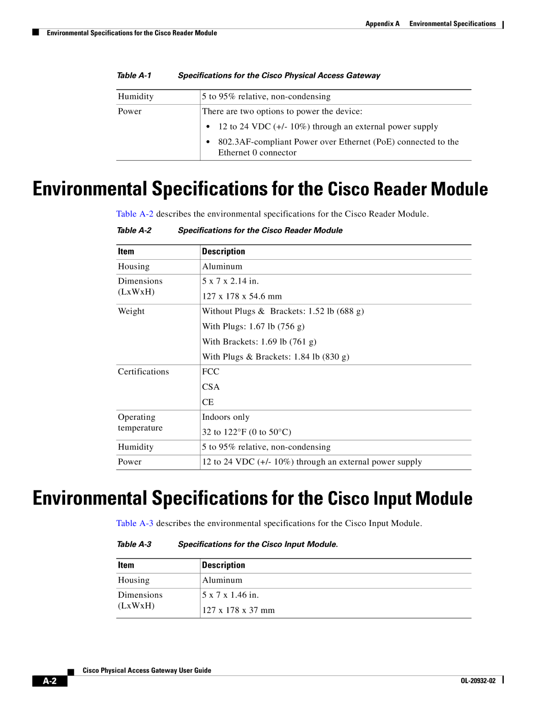
Environmental Specifications for the Cisco Reader Module
Table
Table
Item | Description |
|
|
Housing | Aluminum |
|
|
Dimensions | 5 x 7 x 2.14 in. |
(LxWxH) | 127 x 178 x 54.6 mm |
| |
|
|
Weight | Without Plugs & Brackets: 1.52 lb (688 g) |
| With Plugs: 1.67 lb (756 g) |
| With Brackets: 1.69 lb (761 g) |
| With Plugs & Brackets: 1.84 lb (830 g) |
|
|
Certifications | FCC |
| CSA |
| CE |
|
|
Operating | Indoors only |
temperature | 32 to 122°F (0 to 50°C) |
| |
|
|
Humidity | 5 to 95% relative, |
|
|
Power | 12 to 24 VDC (+/- 10%) through an external power supply |
|
|
Environmental Specifications for the Cisco Input Module
Table
Table | Specifications for the Cisco Input Module. | |
|
|
|
Item |
| Description |
|
|
|
Housing |
| Aluminum |
|
|
|
Dimensions |
| 5 x 7 x 1.46 in. |
(LxWxH) |
| 127 x 178 x 37 mm |
|
| |
|
|
|
Cisco Physical Access Gateway User Guide
|
| ||
|
|