Chapter 2 Installing and Configuring the Cisco Physical Access Gateway
Installing the Cisco Physical Access Gateway
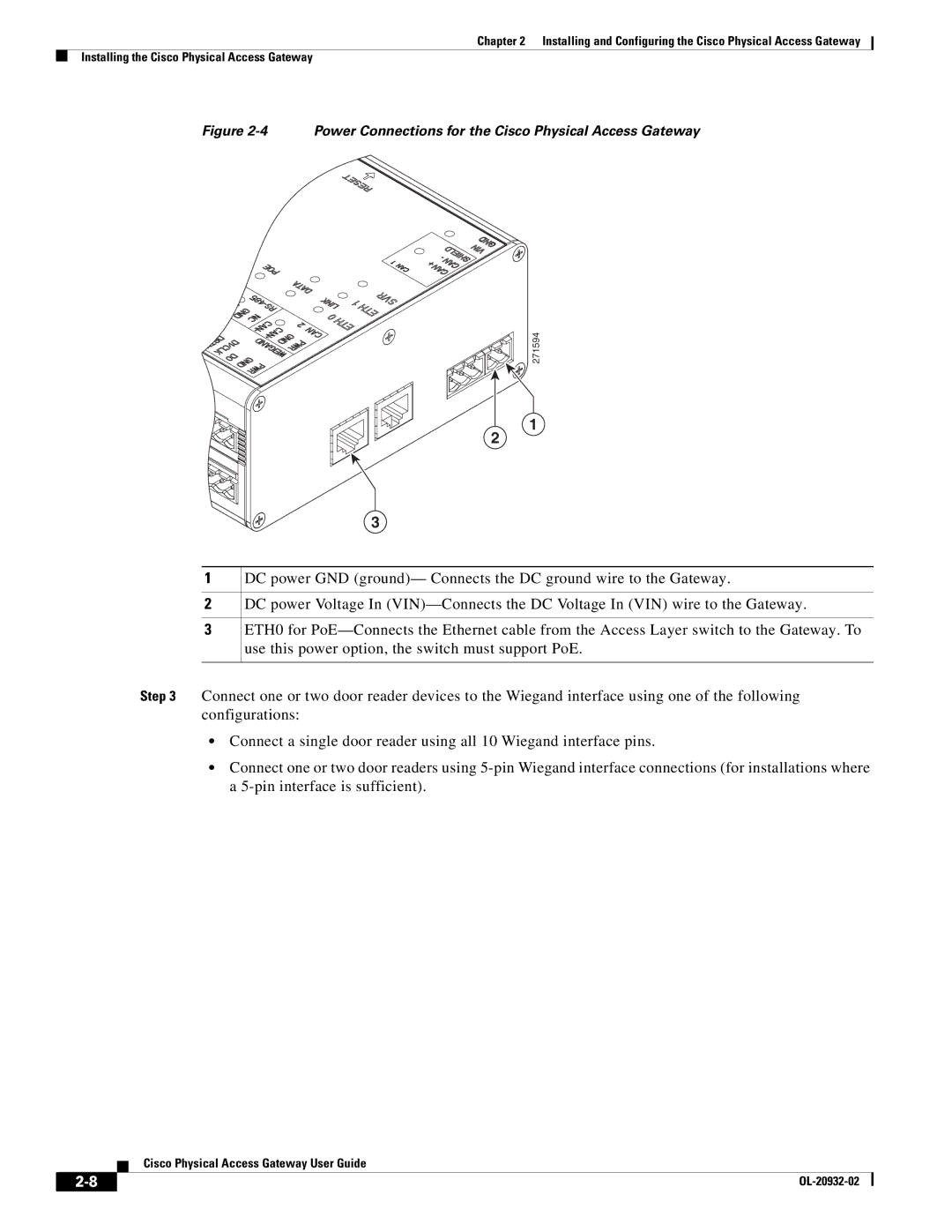
Figure 2-4 Power Connections for the Cisco Physical Access Gateway
271594
1
2
3
1
2
3
DC power GND (ground)— Connects the DC ground wire to the Gateway.
DC power Voltage In
ETH0 for
Step 3 Connect one or two door reader devices to the Wiegand interface using one of the following configurations:
•Connect a single door reader using all 10 Wiegand interface pins.
•Connect one or two door readers using
Cisco Physical Access Gateway User Guide
| ||
|