Chapter 4 Connecting a Cisco Input Module
Installing the Cisco Input Module
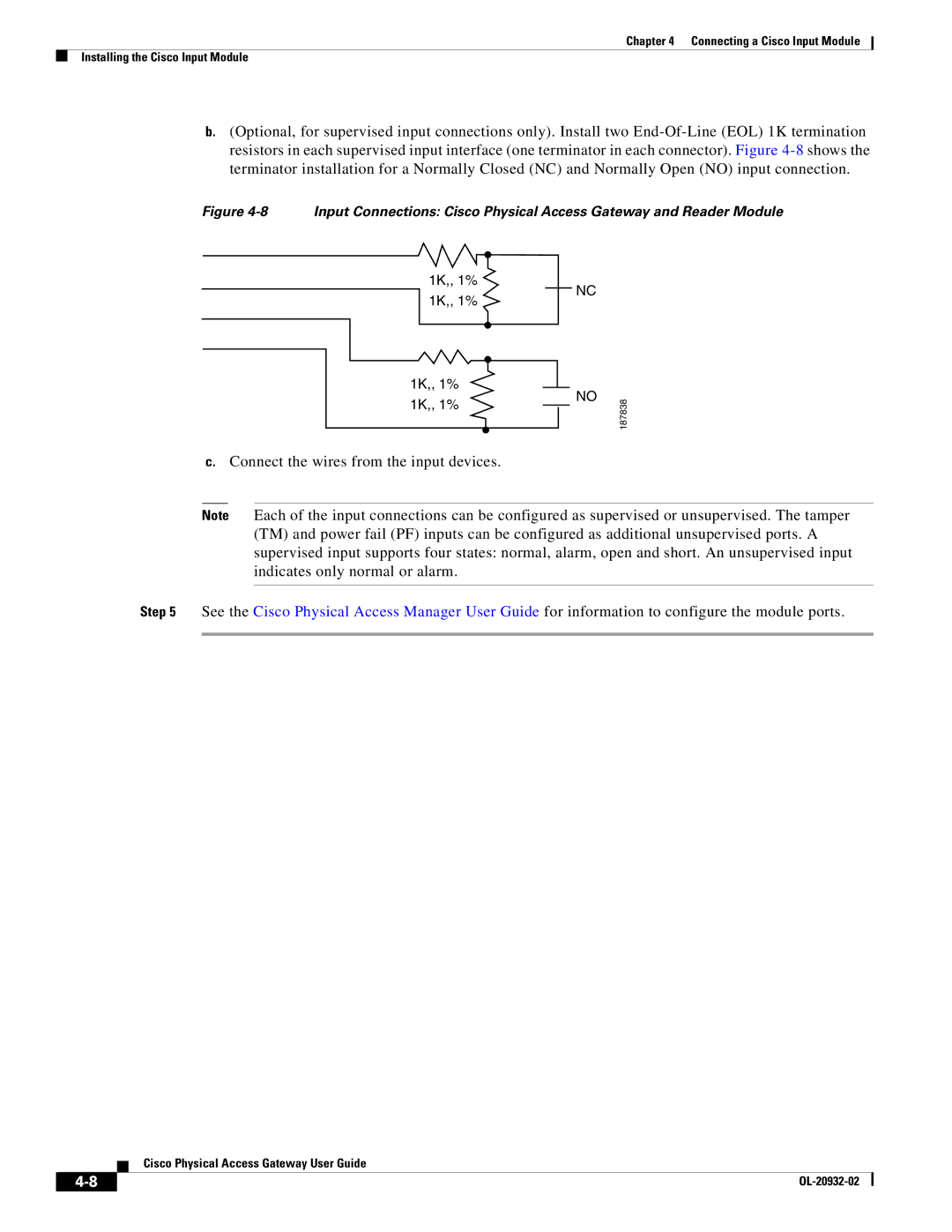
b.(Optional, for supervised input connections only). Install two
Figure 4-8 Input Connections: Cisco Physical Access Gateway and Reader Module
1K,, 1%
NC
1K,, 1%
1K,, 1%
1K,, 1%
NO
187838
c.Connect the wires from the input devices.
Note Each of the input connections can be configured as supervised or unsupervised. The tamper (TM) and power fail (PF) inputs can be configured as additional unsupervised ports. A supervised input supports four states: normal, alarm, open and short. An unsupervised input indicates only normal or alarm.
Step 5 See the Cisco Physical Access Manager User Guide for information to configure the module ports.
Cisco Physical Access Gateway User Guide
| ||
|