Chapter 3 Connecting a Cisco Reader Module
Package Contents
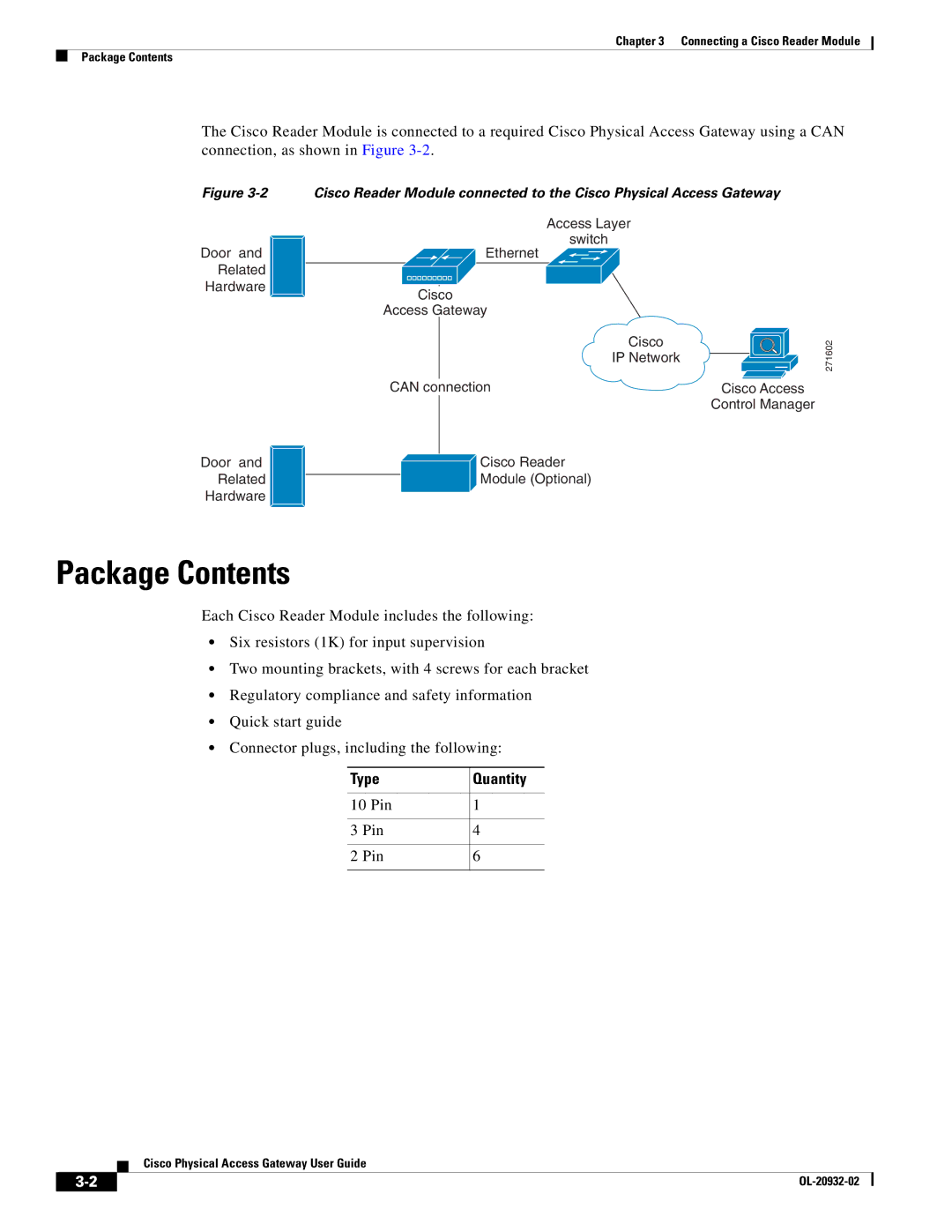
The Cisco Reader Module is connected to a required Cisco Physical Access Gateway using a CAN connection, as shown in Figure
Figure
Door and
Related
Hardware
Door and
Related
Hardware
Cisco Reader Module connected to the Cisco Physical Access Gateway
Access Layer
switch
Ethernet
Cisco
Access Gateway
Cisco
IP Network
CAN connection | Cisco Access |
| Control Manager |
![]() Cisco Reader
Cisco Reader
Module (Optional)
271602
Package Contents
Each Cisco Reader Module includes the following:
•Six resistors (1K) for input supervision
•Two mounting brackets, with 4 screws for each bracket
•Regulatory compliance and safety information
•Quick start guide
•Connector plugs, including the following:
Type | Quantity |
|
|
10 Pin | 1 |
|
|
3 Pin | 4 |
|
|
2 Pin | 6 |
|
|
Cisco Physical Access Gateway User Guide
| ||
|
