SPECIFICATIONS
A
B
CONTROL
TPBS002/1199
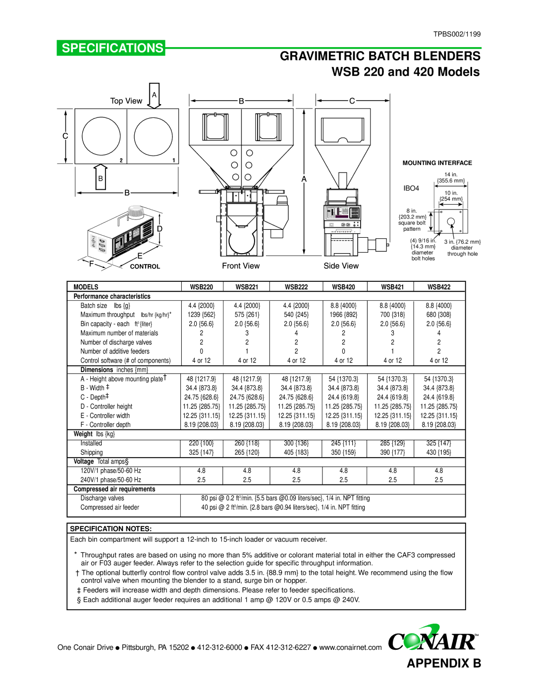
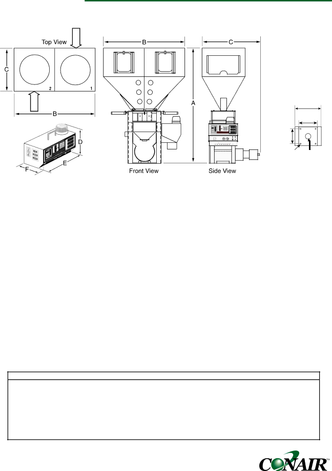
GRAVIMETRIC BATCH BLENDERS WSB 220 and 420 Models
MOUNTING INTERFACE
|
|
|
| 14 in. |
|
|
|
| {355.6 mm} |
|
|
| IBO4 | 10 in. |
|
|
|
| |
|
|
|
| {254 mm} |
0 | 0 | 0 | 8 in. |
|
0 | 0 | 0 |
| |
0 | 0 | 0 | {203.2 mm} |
|
|
|
|
| |
|
|
| square bolt |
|
|
|
| pattern |
|
|
|
| (4) 9/16 in. | 3 in. {76.2 mm} |
|
|
| {14.3 mm} | diameter |
|
|
| diameter | through hole |
|
|
| bolt holes |
|
MODELS |
| WSB220 | WSB221 | WSB222 | WSB420 |
| WSB421 | WSB422 |
Performance characteristics |
|
|
|
|
|
|
| |
Batch size lbs {g} |
| 4.4 {2000} | 4.4 {2000} | 4.4 {2000} | 8.8 {4000} |
| 8.8 {4000} | 8.8 {4000} |
Maximum throughput | lbs/hr {kg/hr}* | 1239 {562} | 575 {261} | 540 {245} | 1966 {892} |
| 700 {318} | 680 {308} |
Bin capacity - each | ft3 {liter} | 2.0 {56.6} | 2.0 {56.6} | 2.0 {56.6} | 2.0 {56.6} |
| 2.0 {56.6} | 2.0 {56.6} |
Maximum number of materials | 2 | 3 | 4 | 2 |
| 3 | 4 | |
Number of discharge valves | 2 | 2 | 2 | 2 |
| 2 | 2 | |
Number of additive feeders | 0 | 1 | 2 | 0 |
| 1 | 2 | |
Control software (# of components) | 4 or 12 | 4 or 12 | 4 or 12 | 4 or 12 |
| 4 or 12 | 4 or 12 | |
Dimensions inches {mm} |
|
|
|
|
|
|
| |
A - Height above mounting plate† | 48 {1217.9} | 48 {1217.9} | 48 {1217.9} | 54 {1370.3} |
| 54 {1370.3} | 54 {1370.3} | |
B - Width ‡ |
| 34.4 {873.8} | 34.4 {873.8} | 34.4 {873.8} | 34.4 {873.8} |
| 34.4 {873.8} | 34.4 {873.8} |
C - Depth‡ |
| 24.75 {628.6} | 24.75 {628.6} | 24.75 {628.6} | 24.4 {619.8} |
| 24.4 {619.8} | 24.4 {619.8} |
D - Controller height |
| 11.25 {285.75} | 11.25 {285.75} | 11.25 {285.75} | 11.25 {285.75} |
| 11.25 {285.75} | 11.25 {285.75} |
E - Controller width |
| 12.25 {311.15} | 12.25 {311.15} | 12.25 {311.15} | 12.25 {311.15} |
| 12.25 {311.15} | 12.25 {311.15} |
F - Controller depth |
| 8.19 {208.03} | 8.19 {208.03} | 8.19 {208.03} | 8.19 {208.03} |
| 8.19 {208.03} | 8.19 {208.03} |
Weight lbs {kg} |
|
|
|
|
|
|
|
|
|
|
|
|
|
|
|
|
|
Installed |
| 220 {100} | 260 {118} | 300 {136} | 245 {111} |
| 285 {129} | 325 {147} |
Shipping |
| 325 {147} | 265 {120} | 405 {183} | 350 {159} |
| 390 {177} | 430 {195} |
|
|
|
|
|
|
|
|
|
Voltage Total amps§ |
|
|
|
|
|
|
|
|
120V/1 | 4.8 | 4.8 | 4.8 | 4.8 |
| 4.8 | 4.8 | |
240V/1 | 2.5 | 2.5 | 2.5 | 2.5 |
| 2.5 | 2.5 | |
Compressed air requirements |
|
|
|
|
|
|
| |
Discharge valves |
| 80 psi @ 0.2 ft3/min. {5.5 bars @0.09 liters/sec}, 1/4 in. NPT fitting |
|
| ||||
Compressed air feeder | 40 psi @ 2 ft3/min. {2.8 bars @0.94 liters/sec}, 1/4 in. NPT fitting |
|
| |||||
|
|
|
|
|
|
|
|
|
SPECIFICATION NOTES:
Each bin compartment will support a
*Throughput rates are based on using no more than 5% additive or colorant material total in either the CAF3 compressed air or F03 auger feeder. Always refer to the selection guide for specific throughput information.
†The optional butterfly control flow control valve adds 3.5 in. {88.9 mm} to the total height. We recommend using the flow control valve when mounting the blender to a stand, surge bin or hopper.
‡Feeders will increase width and depth dimensions. Please refer to feeder specifications.
§ Each additional auger feeder requires an additional 1 amp @ 120V or 0.5 amps @ 240V.
One Conair Drive ● Pittsburgh, PA 15202 ●
APPENDIX B