Web/Installation Guide
Table of Contents
Managing Device Information
Configuring Ports 115
Configuring IP Information 171
Configuring Quality of Service 237
Configuring System Time 281
Preface
DXS/DWS-3227/3227P, DXS/DWS-3250 User Guide Overview
DXS/DWS-3227/3227P, DXS/DWS-3250 User Guide Overview
DXS/DWS 3200 Series User Guide
Intended Audience
Viewing the Device
Device Description
DXS-3250/DWS Front Panel
Viewing the Device
DXS/DWS-3227P Front Panel
DXS/DWS-3227 Front Panel
DXS/DWS-3227P Front Panel
Back Panels
1000Base-T Gigabit Ethernet Ports
Ports Description
10G XFP Fiber port
Optional Modules
SFP Ports
10G XFP Fiber port
Ports Description
Stacking Ports
RS-232 Console Port
Stacking Kit Optional
LED Definitions
Cable Specifications
Port LEDs
1000Base-T Gigabit Ethernet RJ-45 Port LEDs
LED Definitions
1000Base-T Gigabit Ethernet RJ-45 Port LED Indications
Port Description LED Indication
SFP LEDs
System LEDs
SFP LED Indications Description
Indication
System’s LED Indications LED Description
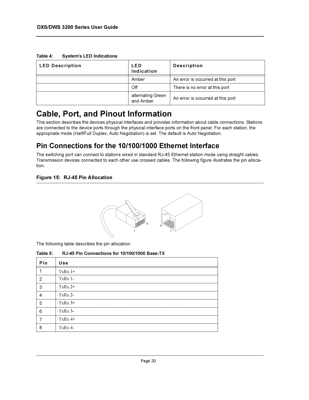
Cable, Port, and Pinout Information
Pin Connections for the 10/100/1000 Ethernet Interface
RJ-45 Pin Connections for 10/100/1000 Base-TX Use
Cable, Port, and Pinout Information
CX-4 Port Pin Connections
Pin Use
DXS/DWS 3250 / DXS/DWS 3227P
Physical Dimensions
DXS/DWS
DB-9 Port Pin Connections Use
Physical Dimensions
DXS/DWS 3200 Series User Guide
Installation Precautions
Preparing for Installation
Preparing for Installation
Mounting Device
Site Requirements
Package Contents
Unpacking
Unpacking Essentials
Desktop or Shelf Installation
Installing the Device
Rack Installation
Installing the Device
Attaching the Mounting Brackets
Mounting Device in a Rack
Connecting the Device
Connecting the Switch to a Terminal
AC Power Connection
General Configuration Information
Initial Configuration
General Configuration Information
Auto-Negotiation
Booting the Switch
Device Port Default Settings
Device Port Default Settings Function
Booting the Switch
Configuration Overview
Initial Configuration
Configuration Overview
Static IP Address and Subnet Mask
Snmp Community Strings
User Name
Following screen displays the default device configuration
Retrieving an IP Address From a Dhcp Server
Advanced Configuration
Advanced Configuration
Receiving an IP Address From a Bootp Server
Security Management and Password Configuration
Configuring Security Passwords Introduction
Configuring an Initial Console Password
Configuring an Initial SSH password
Configuring an Initial Telnet Password
Configuring an Initial Http Password
Configuring an initial Https Password
Software Download and Reboot
Software Download through XModem
Software Download Through Tftp Server
Software Download and Reboot
Boot Image Download
Configuring Stacking
Configuring Stacking
Download Software
Startup Menu Functions
Erase Flash File
Erase Flash Sectors
Startup Menu Functions
Wlan Licence Key
Password Recovery
Press Escape
Press Enter
This page is left blank intentionally
Getting Started
Click . The D-Link Embedded Web Interface Home Page opens
Starting the D-Link Embedded Web Interface
Starting the D-Link Embedded Web Interface
Link Embedded Web Interface Home
Understanding the D-Link Embedded Web Interface
Interface Components
View Description
Understanding the D-Link Embedded Web Interface
Device Representation
Using the D-Link Embedded Web Interface Management Buttons
Adding Configuration Information
Using Screen and Table Options
Modifying Configuration Information
Using Screen and Table Options
IP Interface Settings
Deleting Configuration Information
Resetting the Device
Resetting the Device
Click System General Reset. The Reset page opens
Click . The D-Link Embedded Web Interface Home Page closes
Logging Off from the Device
Managing Device Information
Defining the System Description
Defining the System Description
DXS/DWS 3200 Series User Guide
Defining Advanced System Settings
Defining Advanced System Settings
Click System General Mode. The Mode Page opens
Check the Enable Jumbo Frames field
This page is left blank intentionally
Managing Power over Ethernet Devices
Defining PoE System Information
Modify the Unit No., Power Status, and Powered Device fields
Define the Unit No. and the System Usage Threshold field
Defining PoE System Information
PoE Interface
Displaying and Editing PoE System Information
Click . The PoE Interface Edit Page opens
Displaying and Editing PoE System Information
DXS/DWS 3200 Series User Guide
Managing Stacking
Understanding the Stack Topology
Stacking Failover Topology
Stacking Members and Unit ID
Stacking Failover Topology
Removing and Replacing Stacking Members
Exchanging Stacking Members
Switching the Stacking Master
Click System General tab. The Stack Page opens
Stack Page contains the following fields
This page is left blank intentionally
Configuring Device Security
Configuring Authentication Methods
Configuring Management Security
Configuring Management Security
Defining Access Profiles
Click . The Add Access Profile Page opens
Add Access Profile
Configuring Device Security
Profile Rules
Defining Profile Rules
Click . The Add Profile Rule Page opens
Add Profile Rule
Click . The Profile Rules Setting Page opens
Authentication Profile
Defining Authentication Profiles
Click . The Add Authentication Profile Page opens
Add Authentication Profile
Authentication Mapping
Mapping Authentication Methods
Define the Console, Telnet, and Secure Telnet SSH fields
Radius
Defining Radius Settings
Click . The Add Radius Server Page opens
Add Radius Server
Click . The Radius Server Settings Page opens
Radius Server Settings
TACACS+
Defining TACACS+ Authentication
Add TACACS+ Host
TACACS+ Host Settings
Configuring Passwords
Defining Local Users
Click . The Add Local User Page opens
Click . The Local User Settings Page opens
Local User Settings
Line Password
Defining Line Passwords
Enable Password
Defining Enable Passwords
Port-Based Authentication
Configuring Network Security
Advanced Port-Based Authentication
Configuring Network Security
DXS/DWS 3200 Series User Guide
Network Authentication Properties
Defining Network Authentication Properties
DXS/DWS 3200 Series User Guide
Port Authentication
Defining Port Authentication
Click . The Port Authentication Settings Page opens
Supplicant Timeout Server Timeout
Multiple Host
Configuring Multiple Hosts
Multiple Host Settings
Authenticated Host
Defining Authentication Hosts
Configuring Traffic Control
Port Security
Managing Port Security
Click . The Port Security Settings Page opens
Port Security Settings
Storm Control
Enabling Storm Control
Click . The Storm Control Settings Page opens
Storm Control Settings
Defining DOS Protection Security
Defining DOS Protection Security
Click . The Add Martian Addresses Page opens
Add Martian Addresses
Interface Configuration
Configuring Ports
Click . The Port or LAG Interface Settings Page opens
Port Configuration Settings
Configuring Ports
Interface Properties
Viewing Port Properties
Viewing Port Properties
Port Properties
This page is left blank intentionally
Aggregating Ports
Click . The Lacp Parameters Settings Page opens
Configuring Lacp
Edit the Port Priority and Lacp Timeout fields
Configuring Lacp
LAG Membership
Defining LAG Members
Configuring VLANs
Vlan Properties
Defining Vlan Properties
Defining Vlan Properties
Add Vlan
Vlan Membership
Defining Vlan Membership
Defining Vlan Membership
Vlan Interface Settings
Defining Vlan Interface Settings
Click . The Vlan Interface Settings Page opens
Defining Vlan Interface Settings
Defining Garp
Configuring Garp
Click . The Garp Parameters Settings Page opens
Configuring Garp
Gvrp Parameters
Defining Gvrp
Click . The Gvrp Parameters Settings Page opens
Gvrp Parameters Settings
Configuring Multicast VLANs
Defining Vlan Groups
Defining Protocol Based VLANs
Defining Vlan Groups
Add Protocol Group
Defining Vlan Protocol Ports
Click . The Vlan Protocol Port Setting Page opens
Click . The Protocol Group Settings Page opens
Vlan Protocol Port Setting
Defining Wlan
Enabling Wlan
Defining Wlan System Properties
Defining Wlan Security
Defining Wlan System Properties
Click Wlan System ESS/Security. The ESS Security Page opens
Click . The Create ESS Configuration Page opens
Create ESS Configuration
ESS Settings
DXS/DWS 3200 Series User Guide
Click Wlan System Rogues. The Wlan Rogues Page opens
Viewing Wlan Rogues
DXS/DWS 3200 Series User Guide
Monitor Wlan Stations
Viewing Wlan Stations
Defining Wlan Access Points
Defining Wlan Access Points
Defining Wlan Access Point Properties
WTP Edit Screen
Adding a New Access point
Wlan Access Point VLANs
Configuring Wlan VLANs
Click . The Create Wlan Template Page opens
Configuring Wlan Template Settings
Create Wlan Template
Defining Wlan Radio Settings
Configuring Wlan Radio Settings
Click . The Modify Radio Setting Page opens
Configuring Wlan Radio Settings
Click Wlan Radio BSS Settings. The BSS Settings Page opens
Defining BSS Settings
Click . The Create AP BSS Configuration Page opens
Click . The Edit BSS Settings Page opens
Create AP BSS Configuration
Edit BSS Settings
Wlan Radio Power Settings
Defining Wlan Power Settings
Defining Wlan
Viewing Wlan Statistics
Viewing Access Point Statistics
Viewing Wlan Statistics
Wlan Radio Interface Statistics
Viewing Radio Interfaces Statistics
Defining Wlan
Click Wlan Monitor BSS. The BSS Information Page opens
Viewing BSS Statistics
Wlan Stations Statistics
DXS/DWS 3200 Series User Guide
Configuring IP Information
Configuring IP Interfaces
Configuring IP Interfaces
Click . The Add IP Interface Page opens
Defining IP Addresses
Add IP Interface
Click . The IP Interface Settings Page opens
Default Gateway
Defining Default Gateways
Click . The Add Dhcp IP Interface Page opens
Configuring Dhcp
Add Dhcp IP Interface
ARP
Configuring ARP
ARP Settings
Configuring Domain Name Servers
Configuring Domain Name Servers
Defining DNS Servers
Click . The Add DNS Server Page opens
Remove
DNS Host Mapping
Defining DNS Host Mapping
Add DNS Host
Defining the Forwarding Database and Static Routes
Forwarding Database Static Addresses
Defining Static Forwarding Database Entries
Defining Static Forwarding Database Entries
Add Forwarding Database
Dynamic Addresses
Defining Dynamic Forwarding Database Entries
Defining Dynamic Forwarding Database Entries
IP Static Route
Configuring Routing
Configuring Routing
DXS/DWS 3200 Series User Guide
Configuring Spanning Tree
STP Properties
Defining Classic Spanning Tree
Defining Classic Spanning Tree
Select Enable in the Spanning Tree State field
STP Interface
Defining STP on Interfaces
Defining STP on Interfaces
Click . The STP Interface Settings Page opens
DXS/DWS 3200 Series User Guide
Defining Rapid Spanning Tree
Defining Rapid Spanning Tree
Defining Multiple Spanning Tree
Click . The Rstp Settings Page opens
Define the Region Name, Revision, and Max Hops fields
Defining Multiple Spanning Tree
Click . The Mstp Instance Configuration Table opens
Defining Mstp Instance Settings
Mstp Instance Configuration Table
Mstp Interface Settings Page contains the following fields
Defining Mstp Interface Settings
Click . The Mstp Interface Table opens
This page is left intentionally
Configuring Multicast Forwarding
Igmp Snooping
Defining Igmp Snooping
Defining Igmp Snooping
Multicast Global Parameters Settings
Multicast Group
Defining Multicast Bridging Groups
Click . The Add Multicast Group Page opens
Defining Multicast Bridging Groups
Multicast Forward All
Defining Multicast Forward All Settings
Forbidden
Defining Igmp Snooping for Multicast TV
Configuring Multicast TV
Click . The Add Igmp Snooping Mapping Page opens
Configuring Multicast TV
Multicast TV Membership
Viewing Multicast TV Members
Configuring Snmp Security
Configuring Snmp
Snmp v1 and v2c
Snmp
Defining Snmp Security
Define the Local Engine ID and Use Default fields
Defining Snmp Views
Configuring Snmp Security
Add Snmp View
Snmp Group Profile
Defining Snmp Group Profiles
Click . The Add Snmp Group Profile Page opens
Click . The Snmp Group Profile Settings Page opens
Snmp Group Profile Settings
Snmp Group Membership
Defining Snmp Group Members
Click . The Add Snmp Group Membership Page opens
Click . The Snmp Group Membership Settings Page opens
Snmp Group Membership Settings
Snmp Communities Basic Table
Defining Snmp Communities
Click . The Add Snmp Community Page opens
Snmp Communities Advanced Tables
Configuring Snmp Notifications
Configuring Snmp Notifications
Click . The Snmp Community Settings Page opens
Snmp Notification Properties
Defining Snmp Notification Global Parameters
Click . The Add Snmp Notification Filter Page opens
Defining Snmp Notification Filters
Add Snmp Notification Filter
Snmp Notification Receiver
Defining Snmp Notification Recipients
SNMPv1,2c Notification Recipient
Click . The Add Snmp Notification Receiver Page opens
SNMPv3 Notification Recipient
Add Snmp Notification Receiver
Click . The Snmp Notification Receiver Settings Page opens
Snmp Notification Receiver Settings
This page is left blank intentionally
Configuring Quality of Service
Defining General QoS Settings
Quality of Service Overview
CoS Services
Configuring QoS General Settings
CoS
Defining General QoS Settings
Select Enable in the Quality of Service field
Configure Bandwidth Settings
Restoring Factory Default QoS Interface Settings
Click . The Bandwidth Settings Edit Page opens
Bandwidth Settings Edit
Select Strict Priority or WRR Fields
Defining Queues
Mapping CoS Values to Queues
Configuring QoS Mapping
Mapping Dscp Values to Queues
Configuring QoS Mapping
Defining Policy Properties
Configuring Advanced QoS Settings
Mapping Dscp Values
Configuring Advanced QoS Settings
Tail Drop
Defining Tail Dropping
Class maps
Creating Class Maps
Add Class Map
Click . The Add Aggregated Policier Page opens
Aggregating Policiers
Add Aggregated Policier
Defining Policies
Defining Policy Profiles
Click . The Add QoS Policy Profile Page opens
Add QoS Policy Profile
Policy Binding
Attaching Policies to Interfaces
DXS/DWS 3200 Series User Guide
Managing System Files
File Management Overview
File Management Overview
Firmware Download
Downloading System Files
Downloading System Files
Configuration Download
Open the File Download
Define the Source File Name and Destination File fields
Upload Type
Uploading System Files
Software Image Upload
Configuration Upload
Uploading System Files
Open the File Upload
Active Image
Activating Image Files
Select Copy Configuration
Restoring the Default Configuration File
Select Restore Configuration Factory Defaults
Copying Files
File System
Managing System Files
System Log Severity Levels Message
Managing System Logs
Syslog Properties
Enabling System Logs
Enabling System Logs
Clearing Device Memory Logs
Viewing the Device Memory Logs
Viewing the Flash Logs
Clearing Flash Logs
Viewing the Flash Logs
Click . The Add Syslog Server Page opens
Defining Servers Log Parameters
Defining Servers Log Parameters
Add Syslog Server
This page is left blank intentionally
Managing Device Diagnostics
Port Mirroring
Configuring Port Mirroring
Click . The Add Port Mirroring Page opens
Configuring Port Mirroring
Click . The Port Mirroring Settings Page opens
Port Mirroring Settings
Viewing Integrated Cable Tests
Viewing Integrated Cable Tests
DXS/DWS 3200 Series User Guide
Viewing Optical Transceivers
Viewing Optical Transceivers
Optical Transceivers Page contains the field
CPU Utilization
Viewing the CPU Utilization
Configuring System Time
Configuring Daylight Savings Time
Configuring Daylight Savings Time
Click System General Time. The Time Page opens
Time
Define the Date, Local Time and Time Zone Offset fields
Configuring Sntp
Configuring Sntp
Polling for Unicast Time Information
Polling for Anycast Time Information
Sntp Properties
Defining Sntp Global Settings
Defining Sntp Global Settings
Sntp Authentication
Defining Sntp Authentication
Click . The Section Add Sntp Authentication page opens
Defining Sntp Authentication
Click System Sntp Servers. The Sntp Servers Page opens
Defining Sntp Servers
Click . The Add Sntp Server Page opens
Defining Sntp Servers
Click . The Add Sntp Interface Page opens
Defining Sntp Interface Settings
Define the Interface and Receive Server Updates fields
Defining Sntp Interface Settings
This page is left blank intentionally
Viewing Statistics
Viewing Interface Statistics
Viewing Interface Statistics
Receive Statistics
Viewing Device Interface Statistics
Resetting Interface Statistics Counters
Transmit Statistics
Open the Interface Statistics
Port Utilization
Viewing Port Utilization Statistics
Etherlike Statistics
Viewing Etherlike Statistics
Open the Etherlike Statistics
Resetting Etherlike Statistics Counters
Gvrp Statistics
Viewing Gvrp Statistics
Open the Gvrp Statistics
Resetting Gvrp Statistics Counters
EAP Statistics
Viewing EAP Statistics
DXS/DWS 3200 Series User Guide
Managing Rmon Statistics
Managing Rmon Statistics
Rmon Statistics
Viewing Rmon Statistics
Open the Rmon Statistics
Resetting Rmon Statistics Counters
Defining Rmon History Control
Configuring Rmon History
Click . The Rmon History Control Settings Page opens
Rmon History Control Settings
Rmon History Table
Viewing the Rmon History Table
Viewing Statistics
Defining Rmon Events Control
Configuring Rmon Events
Viewing Statistics
Rmon Events Logs
Viewing the Rmon Events Logs
Click Advanced Setup Rmon Alarm. The Rmon Alarm Page opens
Defining Rmon Alarms
Add Alarms Entry
Appendix A, Wlan Country Settings
Czech
Cyprus
Republic
Germany
Appendix A, Wlan Country Settings
Israel
E q u e n c y R a n g e Ireland
India
Iceland
Korea
E q u e n c y R a n g e
Lithuania
Luxembourg
New Zealand
Norway
Philippines
Poland
Singapore
E q u e n c y R a n g e Sweden
Slovenia
Slovak
E q u e n c y R a n g e United States
America
South Africa
Appendix B, Device Specifications & Features
Hardware Specifications
Appendix B, Device Specifications & Features
A t u r e S c r i p t i o n
DXS-3227, DXS-3227P, and DXS-3250 Features
Lacp
Active underlying Spanning Tree Protocol Features topology
Media-Dependent Interface with Crossover Mdix
MDI/MDIX Support
Simple Network Management Protocol Snmp over the UDP/IP
Security Global Parameters
Sntp
Based on either the Vlan tag or based on a combination
This page is left blank intentionally
Appendix B, Troubleshooting
Appendix B, Troubleshooting
Problem Management
Troubleshooting Solutions
Problems Possible Cause Solution
Troubleshooting Solutions
Console #reload
Contacting D-Link Technical Support
Contacting D-Link Technical Support
DXS/DWS 3200 Series User Guide
Contacting D-Link Technical Support
DXS/DWS 3200 Series User Guide
Contacting D-Link Technical Support
DXS/DWS 3200 Series User Guide
Contacting D-Link Technical Support
DXS/DWS 3200 Series User Guide
Contacting D-Link Technical Support
DXS/DWS 3200 Series User Guide
Contacting D-Link Technical Support
DXS/DWS 3200 Series User Guide
Contacting D-Link Technical Support
DXS/DWS 3200 Series User Guide
Contacting D-Link Technical Support
DXS/DWS 3200 Series User Guide
Contacting D-Link Technical Support
DXS/DWS 3200 Series User Guide
Contacting D-Link Technical Support
DXS/DWS 3200 Series User Guide
Contacting D-Link Technical Support
DXS/DWS 3200 Series User Guide
Contacting D-Link Technical Support
DXS/DWS 3200 Series User Guide
Contacting D-Link Technical Support
DXS/DWS 3200 Series User Guide
Contacting D-Link Technical Support
DXS/DWS 3200 Series User Guide
Warranty
Warranty
DXS/DWS 3200 Series User Guide
Warranty
DXS/DWS 3200 Series User Guide
Product Registration
Product Registration
DXS/DWS 3200 Series User Guide
International Offices
International Offices