Dell PowerEdge C6145 Systems
Hardware Owner’s Manual
Regulatory Model B05S
February
Notes, Cautions, and Warnings
Back Panel Features and Indicators
Contents
2 Using the System Setup Program
Hard-Drive Indicator Patterns
Server Menu
Boot Menu
Advanced Menu
Security Menu
Recommended Tools
3 Installing System Components
Safety Instructions
Power Supplies
Expansion-Card Assembly and Expansion Card
6 Contents
Installing a System Board
Contents
Installing the Sensor Board for 2.5” Hard Drive System
4 Troubleshooting Your System
8 Contents
Installing the Sensor Board for 3.5” Hard Drive System
System Board Connectors
Description
Accessing System Features During Startup
About Your System
Keystroke
About Your System
Front-Panel Features and Indicators
Figure 1-1. Front Panel−3.5” x8 Hard Drives With Two Motherboards
Figure 1-2. Front Panel−3.5” x12 Hard Drives With Two Motherboards
12 About Your System
Figure 1-3. Front Panel−2.5” x18 Hard Drives With Two Motherboards
Figure 1-4. Front Panel−2.5” x24 Hard Drives With Two Motherboards
Figure 1-5. Front Panel−2.5” x24 Hard Drives With One Motherboard
Icon
Indicator, Button
Or Connector
graceful shutdown before power to
Activity LED
Hard-Drive Indicator Patterns
Figure 1-6. Hard-Drive Indicators
Hard
Function
Back-Panel Features and Indicators
Expander
Hard Drive
Icon
Indicator, Button
Or Connector
Figure 1-8. Back Panel−One Motherboard
systems, turning off the system using the
Indicator, Button
Or Connector
NOTE When powering on the system, the
NIC Status Indicator Link/Activity
NIC Indicator Codes
Figure 1-9. NIC Indicators
NIC Status Indicator Speed
Condition
Figure 1-10. NIC Indicators BMC Management Port
NIC Status Indicator Speed
NIC Status Indicator Link/Activity
20 About Your System
Power and System Board Indicator Codes
Condition
Power Supply Indicator Codes
Figure 1-11. Power Supply Status Indicator
AC Power LED
22 About Your System
BMC Heart Beat LED
Figure 1-12. BMC Heart Beat LED
BMC heart beat LED
Collecting System Event Log SEL for Investigation
Post Error Code
Post Error Code Event
About Your System
Other Information You May Need
Using the System Setup Program
System Setup Options at Boot
Start Menu
Console Redirection
28 Using the System Setup Program
Main Menu
Main Screen
Using the System Setup Program
Processor
BIOS Firmware
System Firmware
Product Information
CountDisplays the physical processor count
System Memory
Displays the total system memory size installed on the system
Using the System Setup Program
32 Using the System Setup Program
Advanced Menu
CPU Configuration
Option
Description
Description
CPU Configuration
Scroll to this item and press Enter to view the following screen
Option
Auto Mode default
Option
Description
Maximum Performance
Power Management Maximum Performance
Option
Description
Option
Power Management OS Control
P-state 0 default
Using the System Setup Program
Description
Power Management Advanced Platform Management Link
38 Using the System Setup Program
Option
Option
Memory Configuration
Using the System Setup Program
Scroll to this item and press Enter to view the following screen
Description
IDE Configuration
Native IDE default
Option
function for that port will not work
Using the System Setup Program
Option
Description
Description
AHCI Port0
42 Using the System Setup Program
Option
Description
USB Configuration
Scroll to this item and press Enter to view the following screen
Option
Option
PCI Configuration
Option
Description
Using the System Setup Program
Option
Description
Description
PCIE Slot/Onboard LAN/Mezzing Slot ASPM
46 Using the System Setup Program
Option
Option
NB-SB Port Features
Using the System Setup Program
Scroll to this item and press Enter to view the following screen
48 Using the System Setup Program
Hyper Transport Configuration
Scroll to this item and press Enter to view the following screen
Boot Menu
This page enables you to set POST boot parameters
Using the System Setup Program
Description
Boot Settings Configuration
Select this item and press Enter to view the following submenu items
Option
Description
Boot Device Priority
Select this item and press Enter to view the following submenu items
Option
52 Using the System Setup Program
Hard Disk Drives
Removable Drives
Using the System Setup Program
Scroll to this item and press Enter to view the following screen
54 Using the System Setup Program
CD/DVD Drives
USB Drives
Using the System Setup Program
Scroll to this item and press Enter to view the following screen
56 Using the System Setup Program
Network Drives
Scroll to this item and press Enter to view the following screen
Security Menu
This page enables you to set the security parameters
Using the System Setup Program
Option
Full Access default
Full Access default
Full Access default
Option
Server Menu
Power Off default
Immediate default
60 Using the System Setup Program
System Management
Description
Remote Access Configuration
115200 8,n,1 default
Option
62 Using the System Setup Program
Option
Description
BMC will reset
IPMI Configuration
Sets the type of BMC NIC from BIOS
Shared default
Description
IP Address Configuration
64 Using the System Setup Program
Option
Description
Subnet Mask Configuration
Using the System Setup Program
Option
Description
Default Gateway IP Configuration
66 Using the System Setup Program
Option
Exit Menu
Option
Description
syscfg --istokenactive=D4tokenid
Command Line Interface for Setup Options
impitool raw command data
syscfg -t=D4tokenid
Description
Setup Option
Using the System Setup Program
Token
Description
Setup Option
70 Using the System Setup Program
Token
Description
Setup Option
Using the System Setup Program
Token
Description
Setup Option
72 Using the System Setup Program
Token
Description
Setup Option
Using the System Setup Program
Token
Description
Setup Option
74 Using the System Setup Program
Token
Using the System Setup Program
Table 2-2. The IPMI Command Table
IPMI Command
Setup Option
Description
IPMI Command
Setup Option
76 Using the System Setup Program
Settings
Table 2-3. The Power Management Settings
Performance Settings
Power Optimized
Installing System Components
Safety Instructions
Recommended Tools
Installing System Components
Inside the System
system-board assembly
power distribution board
Installing a Hard-Drive Blank
Hard Drives
Removing a Hard-Drive Blank
Removing a Hard-Drive Carrier
2 Close the release handle to lock the hard drive in place
Installing a Hard-Drive Carrier
Removing a Hard Drive From a Hard-Drive Carrier
3 Turn the lock lever clockwise to the lock symbol. See Figure
1 Place the hard drive into the hard-drive carrier. See Figure
Installing a Hard Drive Into a Hard-Drive Carrier
Installing System Components
2 Lift the hard drive out of the hard-drive carrier
Table 3-1. PSU and Motherboard Support Matrix
Power Supplies
Recommended Configuration
Full Configuration
Removing a Power Supply
Installing a Power Supply
NOTE The maximum output power is printed on the power supply label
86 Installing System Components
Removing a System-Board Assembly
System-Board Assembly
Installing a System-Board Assembly
Air Ducts
Removing the Air Duct
Figure 3-7. Removing and Installing the Air Ducts
Installing the Air Duct
Removing the Heat Sink
Heat Sinks
Figure 3-8. Removing and Installing the Heat Sink
Installing the Heat Sink
Removing a Processor
Processors
3 Remove the heat sink, see Removing the Heat Sink on page
Installing a Processor
Removing the Expansion Card
Expansion-Card Assembly and Expansion Card
latch
Figure 3-11. Removing the Expansion Card
Installing the Expansion Card
9 Replace the screw securing the expansion card
Removing the Expansion-Card Connector
Expansion-Card Connector
Installing the Expansion-Card Connector
Removing the SAS Mezzanine Card
Mezzanine Card
Installing the SAS Mezzanine Card
Removing the 10GbE Mezzanine Card
104 Installing System Components
Figure 3-15. Removing and Installing the 10GbE Mezzanine Card
system-board assembly
Figure 3-16. Removing and Installing the 10GbE Mezzanine Card
Installing the 10GbE Mezzanine Card
Removing the Mezzanine-Card Bridge Board
Mezzanine-Card Bridge Board
Installing the Mezzanine-Card Bridge Board
Supported DIMM Configuration
System Memory
Figure 3-18. Memory Slot Locations
Installing System Components
Table 3-3. Memory Module Configurations and Limitation Memory Unit=GB
110 Installing System Components
Removing the Memory Modules
Installing the Memory Modules
3 memory module socket ejector
Figure 3-19. Installing and Removing a DIMM
112 Installing System Components
memory module
Replacing the System Battery
System Battery
11 Exit the System Setup program
Removing a System Board
System Board
Installing a System Board
Opening the System
Opening and Closing the System
Figure 3-22. Opening and Closing the System
Cooling Fans
Closing the System
Removing a Cooling Fan
cooling fans
Figure 3-23. Removing and Installing a Cooling Fan
Installing a Cooling Fan
120 Installing System Components
NOTE The fan blades should face the front panel of the system
Removing a Power Distribution Board
Power Distribution Boards
122 Installing System Components
Installing a Power Distribution Board
Figure 3-24. Removing and Installing a Power Distribution Board
2nd power distribution board
Removing the Fan Controller Board
Fan Controller Board
fan controller board
Figure 3-25. Removing and Installing the Fan Controller Board
Installing the Fan Controller Board
Middle Planes
Removing the Middle Planes
Figure 3-26. Removing and Installing the Cooling-Fan Brackets
126 Installing System Components
cooling-fan bracket
upper middle plane
Figure 3-27. Removing and Installing the Upper Middle Plane
Figure 3-28. Removing and Installing the Mid-plane Holder Support
Installing System Components
mid-plane holder
Figure 3-29. Removing and Installing the Mid-plane Holder
Figure 3-30. Removing and Installing the Lower Middle Plane
Installing the Middle Planes
130 Installing System Components
Removing the 3.5 Hard-Drive Backplane
Backplanes
Figure 3-31. Removing and Installing the 3.5 Hard-Drive Cage
132 Installing System Components
3.5 hard-drive cage
3.5 hard-drive cage
Figure 3-32. Removing and Installing the 3.5 Hard-Drive Cage
Installing System Components
front-panel assembly
Installing the 3.5 Hard-Drive Backplane
Removing the Expander Card
Expander Card Optional
Figure 3-34. Removing and Installing the 2.5 Hard-Drive Cage
136 Installing System Components
2.5 hard-drive cage
Figure 3-35. Removing and Installing the Hard-Drive Cage
expander card
2.5 hard-drive backplane
Installing the Expander Card
Removing the Front Panel
Front Panels
3-38
Figure 3-39. Removing and Installing a Front Panel
Installing the Front Panel
Removing the Sensor Board for 3.5” Hard Drive System
Sensor Boards
Figure 3-40. Removing and Installing the Sensor Board
144 Installing System Components
sensor board
Installing the Sensor Board for 3.5” Hard Drive System
146 Installing System Components
Removing the Sensor Board for 2.5” Hard Drive System
Installing System Components
Figure 3-41. Removing and Installing the Sensor-Board Assembly
sensor-board assembly
Figure 3-42. Removing and Installing the Sensor Board
148 Installing System Components
Installing the Sensor Board for 2.5” Hard Drive System
Troubleshooting Your System
Safety First - For You and Your System
Installation Problems
Troubleshooting a USB Device
Troubleshooting System Startup Failure
Troubleshooting External Connections
Troubleshooting the Video Subsystem
Troubleshooting a Serial I/O Device
152 Troubleshooting Your System
Troubleshooting a NIC
Troubleshooting a Wet System
Troubleshooting a Damaged System
Troubleshooting the System Battery
154 Troubleshooting Your System
Troubleshooting Power Supplies
Troubleshooting System Cooling Problems
Troubleshooting a Fan
156 Troubleshooting Your System
Troubleshooting System Memory
If the problem is not resolved, proceed with the next step
Troubleshooting a Hard Drive
160 Troubleshooting Your System
Troubleshooting a Storage Controller
Troubleshooting Expansion Cards
162 Troubleshooting Your System
Troubleshooting Processors
IRQ Assignment Conflicts
main power connector
Jumpers and Connectors
System Board Connectors
Figure 5-1. System Board Connectors
23 onboard SATAII connector 25 onboard SATAII connector
11 Hard Drive to backplane SATAII connector
13 Hard Drive to backplane SATAII connector
15 Hard Drive to backplane SATAII connector 17 SGPIO connector
166 Jumpers and Connectors
Backplane Connectors
3.5 Hard-Drive Backplane With CPLD
fan controller board connector
Figure 5-4. Front View of the Backplane
2.5 Hard-Drive Backplane With Expander
2.5 Hard-Drive Backplane Expander Card Connectors
Figure 5-5. Back View of the Backplane
Figure 5-6. 2.5 Hard-Drive Backplane Expander Card
Figure 5-7. Middle Plane Connectors
Middle Plane Connectors
PCI-E Gen 2 x16 iPass connector
Expansion Card Connectors
Figure 5-8. Expansion Card Connectors
170 Jumpers and Connectors
SGPIO connector B
SAS Mezzanine Card Connectors
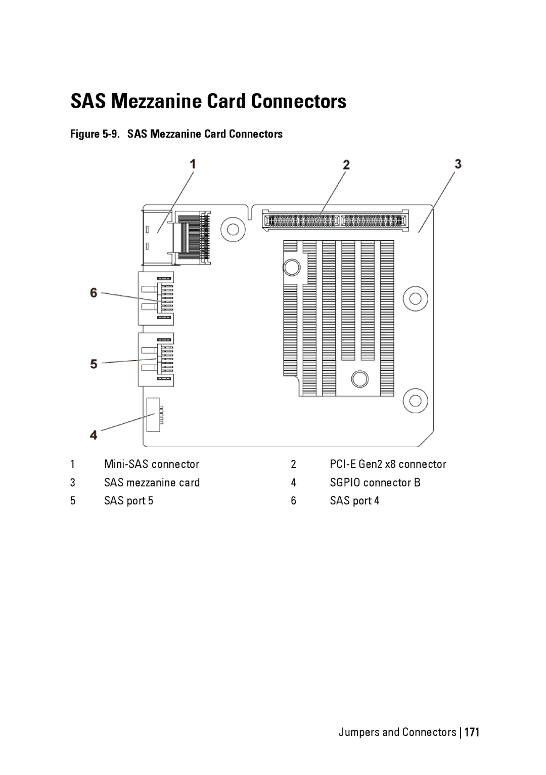
Figure 5-9. SAS Mezzanine Card Connectors
Mini-SAS connector
PCI-E Gen2 x8 connector
10GbE Mezzanine Card Connectors
Figure 5-10. 10GbE Mezzanine Card Connectors
172 Jumpers and Connectors
Figure 5-11. Fan Controller Board Connectors
Fan Controller Board Connectors
PMbus connector
Power Distribution Board Connectors
Figure 5-12. Power Distribution Board Connectors
hard-drive backplane power
Jumpers and Connectors
Sensor Board Connectors
Figure 5-13. Sensor Board Connectors
power connector
Table 5-1. System Configuration Switch
Switch and Jumper Settings
System Configuration Switch Settings
Figure 5-14. System Configuration Switch
Table 5-2. Jumpers Installed on 3.5 Backplane
3.5 Backplane Jumper Settings
2.5 Backplane Expander Card Jumper Settings
Figure 5-15. Jumpers Installed on 3.5 Backplane
Jumper
Figure 5-16. Jumpers Installed on Expander Card
Table 5-3. Jumpers Installed on Expander Card
178 Jumpers and Connectors
Contacting Dell
Getting Help
Index
Page
182 Index
Index