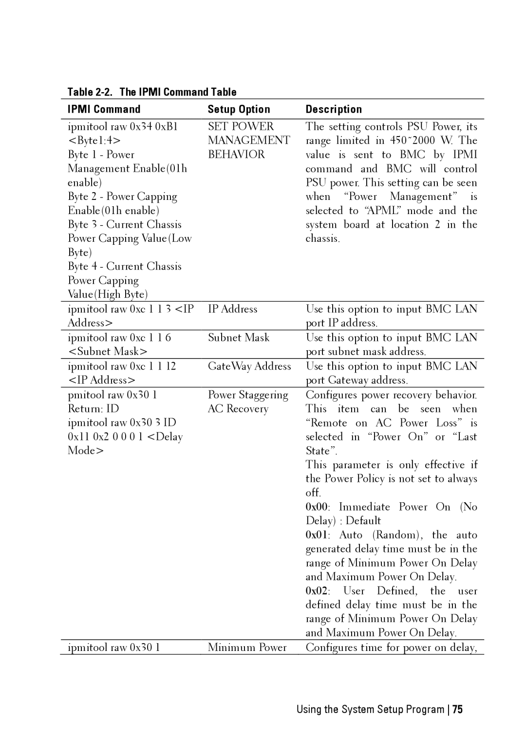
Table 2-2. The IPMI Command Table
IPMI Command | Setup Option | Description |
|
|
|
| |
ipmitool raw 0x34 0xB1 | SET POWER | The setting controls PSU Power, its | |
<Byte1:4> | MANAGEMENT | range limited in 450˜2000 W. The | |
Byte 1 - Power | BEHAVIOR | value is sent to BMC by IPMI | |
Management Enable(01h |
| command and BMC will control | |
enable) |
| PSU power. This setting can be seen | |
Byte 2 - Power Capping |
| when “Power Management” | is |
Enable(01h enable) |
| selected to “APML” mode and the | |
Byte 3 - Current Chassis |
| system board at location 2 in the | |
Power Capping Value(Low |
| chassis. |
|
Byte) |
|
|
|
Byte 4 - Current Chassis |
|
|
|
Power Capping |
|
|
|
Value(High Byte) |
|
|
|
ipmitool raw 0xc 1 1 3 <IP | IP Address | Use this option to input BMC LAN | |
Address> |
| port IP address. |
|
ipmitool raw 0xc 1 1 6 | Subnet Mask | Use this option to input BMC LAN | |
<Subnet Mask> |
| port subnet mask address. |
|
ipmitool raw 0xc 1 1 12 | GateWay Address | Use this option to input BMC LAN | |
<IP Address> |
| port Gateway address. |
|
pmitool raw 0x30 1 | Power Staggering | Configures power recovery behavior. | |
Return: ID | AC Recovery | This item can be seen when | |
ipmitool raw 0x30 3 ID |
| “Remote on AC Power Loss” is | |
0x11 0x2 0 0 0 1 <Delay |
| selected in “Power On” or “Last | |
Mode> |
| State”. |
|
|
| This parameter is only effective if | |
|
| the Power Policy is not set to always | |
|
| off. |
|
|
| 0x00: Immediate Power On (No | |
|
| Delay) : Default |
|
|
| 0x01: Auto (Random), the auto | |
|
| generated delay time must be in the | |
|
| range of Minimum Power On Delay | |
|
| and Maximum Power On Delay. |
|
|
| 0x02: User Defined, the | user |
|
| defined delay time must be in the | |
|
| range of Minimum Power On Delay | |
|
| and Maximum Power On Delay. |
|
ipmitool raw 0x30 1 | Minimum Power | Configures time for power on delay, | |