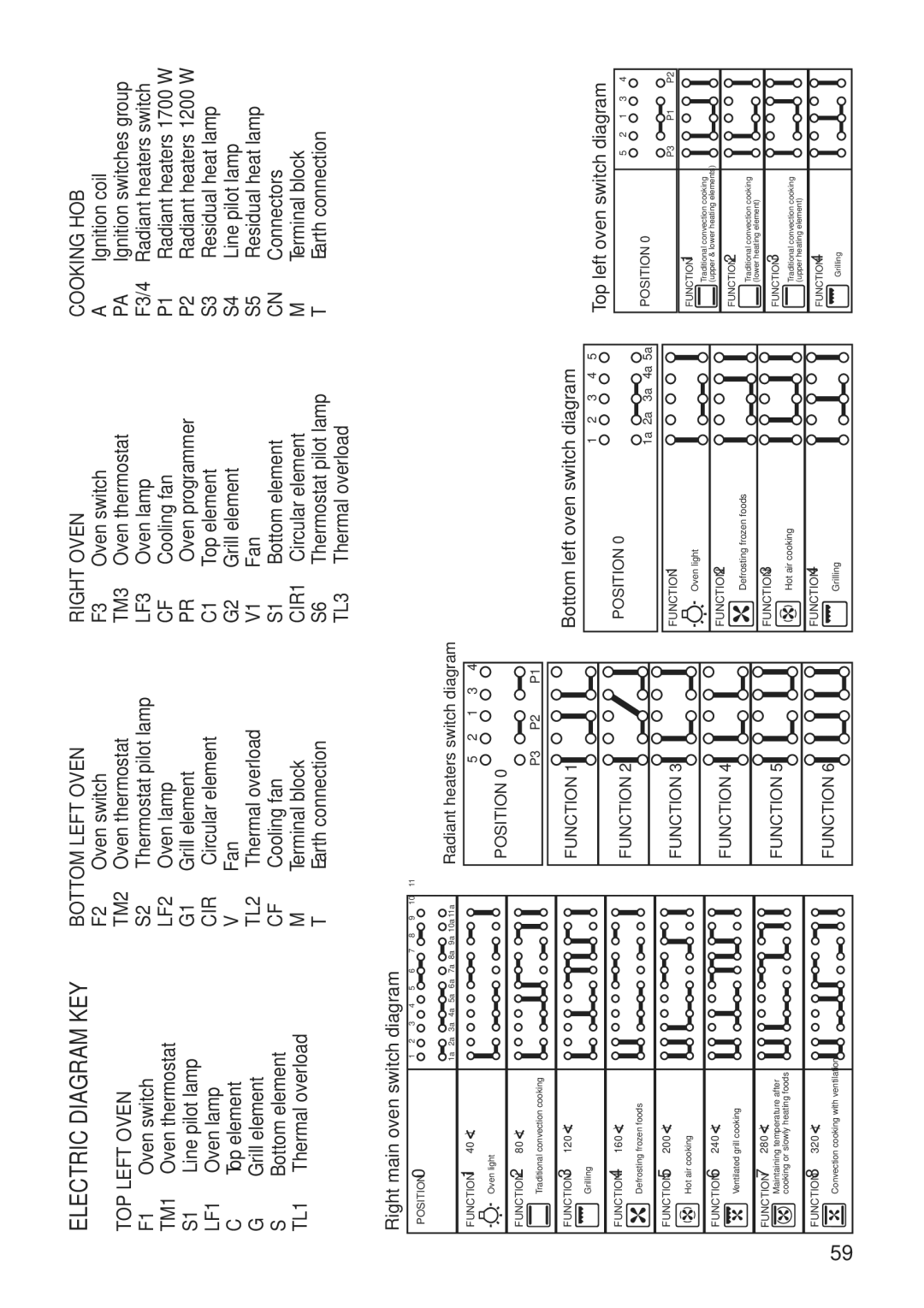
ELECTRIC DIAGRAM KEY | BOTTOM LEFT OVEN | ||
|
| F2 | Oven switch |
TOP LEFT OVEN | TM2 | Oven thermostat | |
F1 | Oven switch | S2 | Thermostat pilot lamp |
TM1 | Oven thermostat | LF2 | Oven lamp |
S1 | Line pilot lamp | G1 | Grill element |
LF1 | Oven lamp | CIR | Circular element |
C | Top element | V | Fan |
G | Grill element | TL2 | Thermal overload |
S | Bottom element | CF | Cooling fan |
TL1 | Thermal overload | M | Terminal block |
|
| T | Earth connection |
RIGHT OVEN | COOKING HOB | ||
F3 | Oven switch | A | Ignition coil |
TM3 | Oven thermostat | PA | Ignition switches group |
LF3 | Oven lamp | F3/4 | Radiant heaters switch |
CF | Cooling fan | P1 | Radiant heaters 1700 W |
PR | Oven programmer | P2 | Radiant heaters 1200 W |
C1 | Top element | S3 | Residual heat lamp |
G2 | Grill element | S4 | Line pilot lamp |
V1 | Fan | S5 | Residual heat lamp |
S1 | Bottom element | CN | Connectors |
CIR1 | Circular element | M | Terminal block |
S6 | Thermostat pilot lamp | T | Earth connection |
TL3 | Thermal overload |
|
|
59
Right main oven switch diagram
POSITION 0 | 1 | 2 | 3 | 4 | 5 | 6 | 7 | 8 | 9 | 10 | 11 |
|
|
|
|
|
|
|
|
|
|
| |
| 1a | 2a | 3a | 4a | 5a | 6a | 7a | 8a | 9a | 10a | 11a |
FUNCTION 1 | 40° ) |
|
|
|
|
|
|
|
|
|
|
Oven light |
|
|
|
|
|
|
|
|
|
|
|
FUNCTION 2 | 80° ) |
|
|
|
|
|
|
|
|
|
|
Traditional convection cooking |
|
|
|
|
|
|
|
|
|
| |
FUNCTION 3 | 120° ) |
|
|
|
|
|
|
|
|
|
|
Grilling |
|
|
|
|
|
|
|
|
|
|
|
FUNCTION 4 | 160° ) |
|
|
|
|
|
|
|
|
|
|
Defrosting frozen foods |
|
|
|
|
|
|
|
|
|
| |
FUNCTION 5 | 200° ) |
|
|
|
|
|
|
|
|
|
|
Hot air cooking |
|
|
|
|
|
|
|
|
|
| |
FUNCTION 6 | 240° ) |
|
|
|
|
|
|
|
|
|
|
Ventilated grill cooking |
|
|
|
|
|
|
|
|
|
| |
FUNCTION 7 | 280° ) |
|
|
|
|
|
|
|
|
|
|
Maintaining temperature after |
|
|
|
|
|
|
|
|
|
| |
cooking or slowly heating foods |
|
|
|
|
|
|
|
|
|
| |
FUNCTION 8 | 320° ) |
|
|
|
|
|
|
|
|
|
|
Convection cooking with ventilation |
|
|
|
|
|
|
|
|
|
| |
Radiant heaters switch diagram
5 2 1 3 4
POSITION 0
P3 P2 P1
FUNCTION 1
FUNCTION 2
FUNCTION 3
FUNCTION 4
FUNCTION 5
FUNCTION 6
Bottom left oven switch diagram
1 2 3 4 5
POSITION 0
1a 2a 3a 4a 5a
FUNCTION 1
Oven light
FUNCTION 2
Defrosting frozen foods
FUNCTION 3
Hot air cooking
FUNCTION 4
Grilling
Top left oven switch diagram
5 2 1 3 4
POSITION 0
P3 P1 P2
FUNCTION 1
Traditional convection cooking (upper & lower heating elements)
FUNCTION 2
Traditional convection cooking (lower heating element)
FUNCTION 3
Traditional convection cooking (upper heating element)
FUNCTION 4
Grilling
