OCX 8800
Instruction Manual
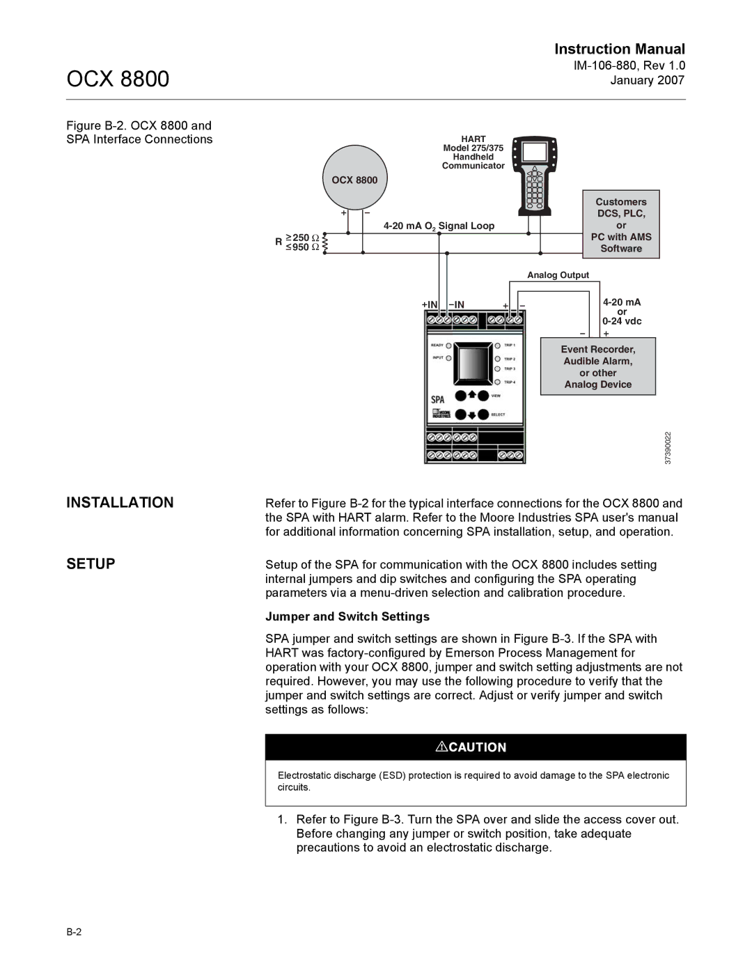
Figure B-2. OCX 8800 and SPA Interface Connections
HART
Model 275/375
Handheld
Communicator
| OCX 8800 |
|
|
| Customers |
|
| DCS, PLC, |
| or | |
| > 250 Ω | PC with AMS |
| R < 950 Ω | Software |
|
| Analog Output |
| IN IN | |
|
| or |
|
| |
|
| Event Recorder, |
|
| Audible Alarm, |
|
| or other |
|
| Analog Device |
|
| 37390022 |
INSTALLATION | Refer to Figure | |
| the SPA with HART alarm. Refer to the Moore Industries SPA user's manual | |
| for additional information concerning SPA installation, setup, and operation. | |
SETUP | Setup of the SPA for communication with the OCX 8800 includes setting | |
| internal jumpers and dip switches and configuring the SPA operating | |
| parameters via a | |
Jumper and Switch Settings
SPA jumper and switch settings are shown in Figure
Electrostatic discharge (ESD) protection is required to avoid damage to the SPA electronic circuits.
1.Refer to Figure