Instruction Manual
IM-106-880, Rev 1.0
January 2007
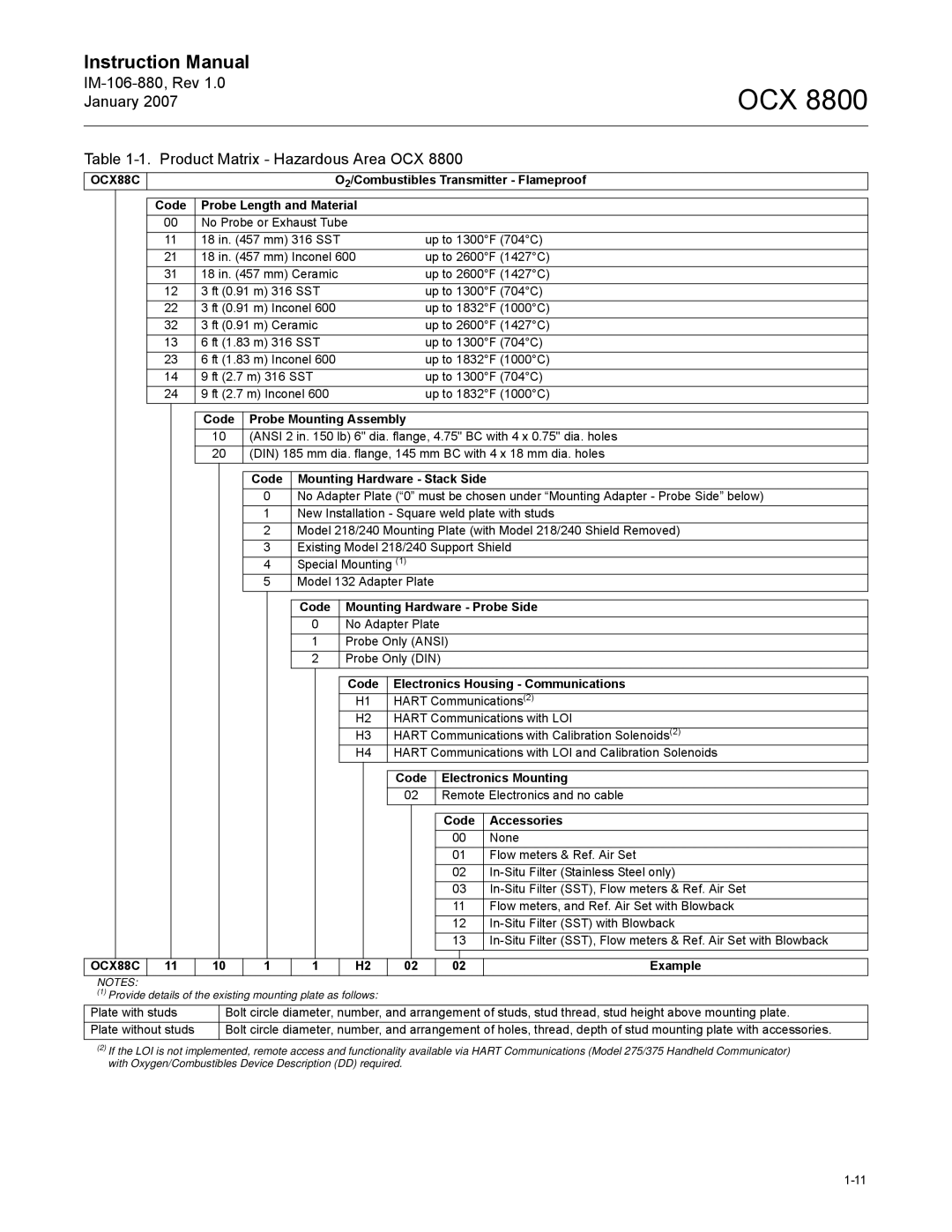
Table 1-1. Product Matrix - Hazardous Area OCX 8800
OCX 8800
OCX88C |
| O2/Combustibles Transmitter - Flameproof | |
|
|
|
|
| Code | Probe Length and Material |
|
| 00 | No Probe or Exhaust Tube |
|
| 11 | 18 in. (457 mm) 316 SST | up to 1300°F (704°C) |
| 21 | 18 in. (457 mm) Inconel 600 | up to 2600°F (1427°C) |
| 31 | 18 in. (457 mm) Ceramic | up to 2600°F (1427°C) |
| 12 | 3 ft (0.91 m) 316 SST | up to 1300°F (704°C) |
| 22 | 3 ft (0.91 m) Inconel 600 | up to 1832°F (1000°C) |
| 32 | 3 ft (0.91 m) Ceramic | up to 2600°F (1427°C) |
| 13 | 6 ft (1.83 m) 316 SST | up to 1300°F (704°C) |
| 23 | 6 ft (1.83 m) Inconel 600 | up to 1832°F (1000°C) |
| 14 | 9 ft (2.7 m) 316 SST | up to 1300°F (704°C) |
| 24 | 9 ft (2.7 m) Inconel 600 | up to 1832°F (1000°C) |
|
|
|
|
|
| Code Probe Mounting Assembly |
|
10(ANSI 2 in. 150 lb) 6" dia. flange, 4.75" BC with 4 x 0.75" dia. holes
20(DIN) 185 mm dia. flange, 145 mm BC with 4 x 18 mm dia. holes
Code | Mounting Hardware - Stack Side |
0 | No Adapter Plate (“0” must be chosen under “Mounting Adapter - Probe Side” below) |
1 | New Installation - Square weld plate with studs |
2 | Model 218/240 Mounting Plate (with Model 218/240 Shield Removed) |
3 | Existing Model 218/240 Support Shield |
4 | Special Mounting (1) |
5 | Model 132 Adapter Plate |
Code Mounting Hardware - Probe Side
0No Adapter Plate
1Probe Only (ANSI)
2Probe Only (DIN)
Code | Electronics Housing - Communications |
H1 | HART Communications(2) |
H2 | HART Communications with LOI |
H3 | HART Communications with Calibration Solenoids(2) |
H4 | HART Communications with LOI and Calibration Solenoids |
|
|
|
|
|
|
| Code | Electronics Mounting | |||
|
|
|
|
|
|
| 02 | Remote Electronics and no cable | |||
|
|
|
|
|
|
|
|
|
|
| |
|
|
|
|
|
|
|
|
| Code | Accessories | |
|
|
|
|
|
|
|
|
| 00 | None | |
|
|
|
|
|
|
|
|
| 01 | Flow meters & Ref. Air Set | |
|
|
|
|
|
|
|
|
| 02 | ||
|
|
|
|
|
|
|
|
| 03 | ||
|
|
|
|
|
|
|
|
| 11 | Flow meters, and Ref. Air Set with Blowback | |
|
|
|
|
|
|
|
|
| 12 | ||
|
|
|
|
|
|
|
|
| 13 | ||
|
|
|
|
|
|
|
|
|
|
| |
OCX88C | 11 | 10 | 1 | 1 | H2 | 02 | 02 | Example | |||
NOTES: |
|
|
|
|
|
|
|
|
|
|
|
(1) Provide details of the existing mounting plate as follows: |
|
|
|
|
| ||||||
Plate with studs |
| Bolt circle diameter, number, and arrangement of studs, stud thread, stud height above mounting plate. | |||||||||
Plate without studs |
| Bolt circle diameter, number, and arrangement of holes, thread, depth of stud mounting plate with accessories. | |||||||||
(2)If the LOI is not implemented, remote access and functionality available via HART Communications (Model 275/375 Handheld Communicator) with Oxygen/Combustibles Device Description (DD) required.