Instruction Manual
OCX 8800
NOTE
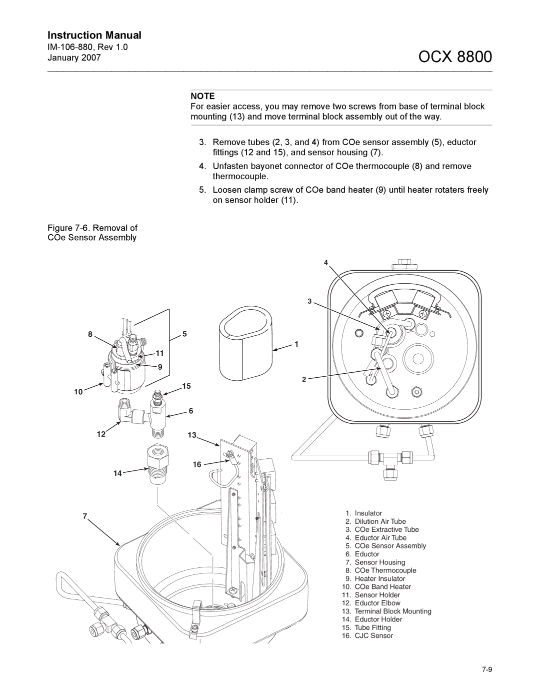
For easier access, you may remove two screws from base of terminal block mounting (13) and move terminal block assembly out of the way.
3.Remove tubes (2, 3, and 4) from COe sensor assembly (5), eductor fittings (12 and 15), and sensor housing (7).
4.Unfasten bayonet connector of COe thermocouple (8) and remove thermocouple.
5.Loosen clamp screw of COe band heater (9) until heater rotaters freely on sensor holder (11).
Figure 7-6. Removal of
COe Sensor Assembly
| 4 |
| |
| 3 |
| |
8 | 5 |
| |
| 1 |
| |
| 11 |
| |
| 9 |
| |
| 2 |
| |
10 | 15 |
| |
|
| ||
| 6 |
| |
12 | 13 |
| |
| 16 |
| |
| 14 |
| |
7 | 1. | Insulator | |
2. | Dilution Air Tube | ||
| |||
| 3. | COe Extractive Tube | |
| 4. | Eductor Air Tube | |
| 5. | COe Sensor Assembly | |
| 6. | Eductor | |
| 7. | Sensor Housing | |
| 8. | COe Thermocouple | |
| 9. | Heater Insulator | |
| 10. | COe Band Heater | |
| 11. | Sensor Holder | |
| 12. | Eductor Elbow | |
| 13. | Terminal Block Mounting | |
| 14. | Eductor Holder | |
| 15. | Tube Fitting | |
| 16. | CJC Sensor |