OCX 8800
Electronics Housing Assembly
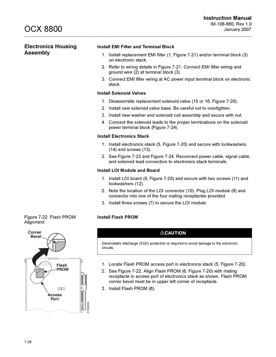
Figure 7-22. Flash PROM Alignment
Corner
Bevel
Flash
![]()
![]()
![]()
![]() PROM
PROM
Access
Port ![]() 37390060
37390060
Instruction Manual
January 2007
Install EMI Filter and Terminal Block
1.Install replacement EMI filter (1, Figure
2.Refer to wiring details in Figure
3.Connect EMI filter wiring at AC power input terminal block on electronic stack.
Install Solenoid Valves
1.Disassemble replacement solenoid valve (15 or 16, Figure
2.Install new solenoid valve base. Be careful not to overtighten.
3.Install new washer and solenoid coil assembly and secure with nut.
4.Connect the solenoid leads to the proper terminations on the solenoid power terminal block (Figure
Install Electronics Stack
1.Install electronics stack (5, Figure
2.See Figure
Install LOI Module and Board
1.Install LOI board (9, Figure
2.Note the location of the LOI connector (10). Plug LOI module (8) and connector into one of the four mating receptacles provided.
3.Install three screws (7) to secure the LOI module.
Install Flash PROM
Electrostatic discharge (ESD) protection is required to avoid damage to the electronic circuits.
1.Locate Flash PROM access port in electronics stack (5, Figure
2.See Figure
3.Install Flash PROM (6).