Instruction Manual
OCX 8800
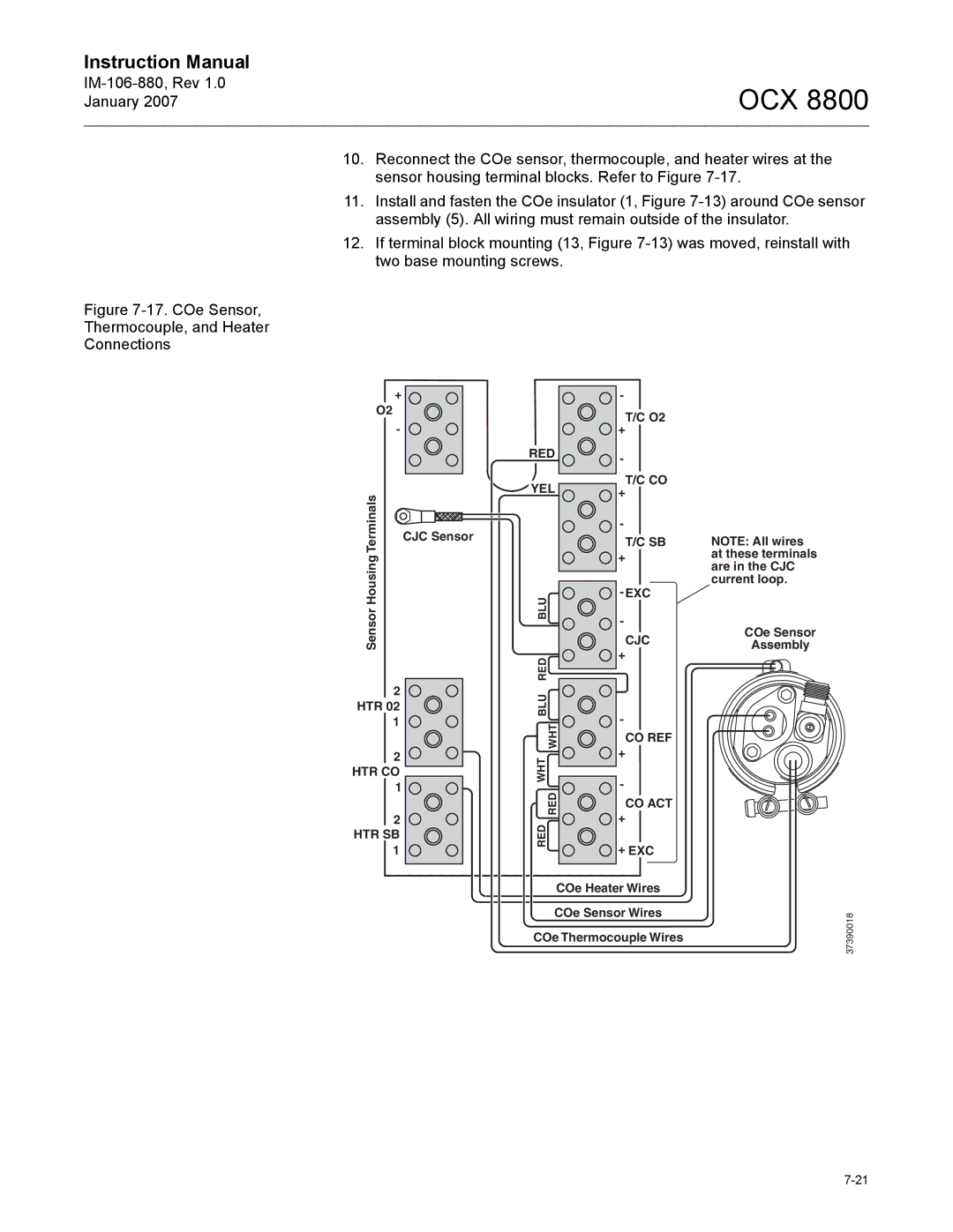
10.Reconnect the COe sensor, thermocouple, and heater wires at the sensor housing terminal blocks. Refer to Figure
11.Install and fasten the COe insulator (1, Figure
12.If terminal block mounting (13, Figure
Figure 7-17. COe Sensor,
Thermocouple, and Heater
Connections
| + | |
| O2 | |
TerminalsHousingSensor | - | |
CJC Sensor | ||
|
2
HTR 02
1
2
HTR CO
1 ![]()
2
HTR SB
1
| - | |
| T/C O2 | |
| + | |
RED | - | |
| ||
YEL | T/C CO | |
+ | ||
| ||
| - | |
| T/C SB | |
| + | |
BLU | ||
- | ||
| ||
| CJC | |
RED | + | |
| ||
BLU | - | |
WHT | ||
CO REF | ||
| ||
WHT | + | |
- | ||
RED | ||
CO ACT | ||
| ||
RED | + | |
+ EXC | ||
|
COe Heater Wires
COe Sensor Wires
COe Thermocouple Wires
NOTE: All wires at these terminals are in the CJC current loop.
COe Sensor
Assembly
37390018