OCX Oxygen/Combustibles Transmitter
Page
Summary
Effective January, 2007 Rev
Page
Table of Contents
Appendix B
Appendix a
Essential Instructions
OCX Oxygen/Combustibles Transmitter
Definitions
Symbols
Preface
Scope System Description
Description and Specifications
Component Checklist System Overview
Typical System Package
OCX
System Features
System Configuration
System Operation
System Considerations
Handling the OCX
OCX 8800 Hart Connections and AMS Application
Integral Electronics
Hazardous Area OCX
Specifications
Power Consumption Maximum
IM-106-880, Rev January Product Matrix Hazardous Area OCX
IM-106-880, Rev 1.0 January Accessories
Section Installation
Selecting Location
Mechanical Installation
Installation
Enclosures
Installation, OCX
Adapter Plate Installation
Installation with Drip Loops
Electrical
Installation
O2 4-20 mA Signal
Connect 4-20 mA Signals
COe 4-20 mA Signal
Alarm Output Relay
TOP View 1/2 Size
Reference Air Set Option only
Pneumatic Installation
HIO LOO
Reference Air Set and Solenoids Option
Reference Air Set, Solenoids, and Blowback Option
Piping Arrangement, Blowback with Autocalibration
Piping Arrangement, Blowback without Autocalibration
Initial Startup
Verify Installation
Configuration and Startup
Verify Configuration
OCX 8800 Defaults
Initial Power UP
SET Test GAS Values
OCX 8800 Reset Procedure
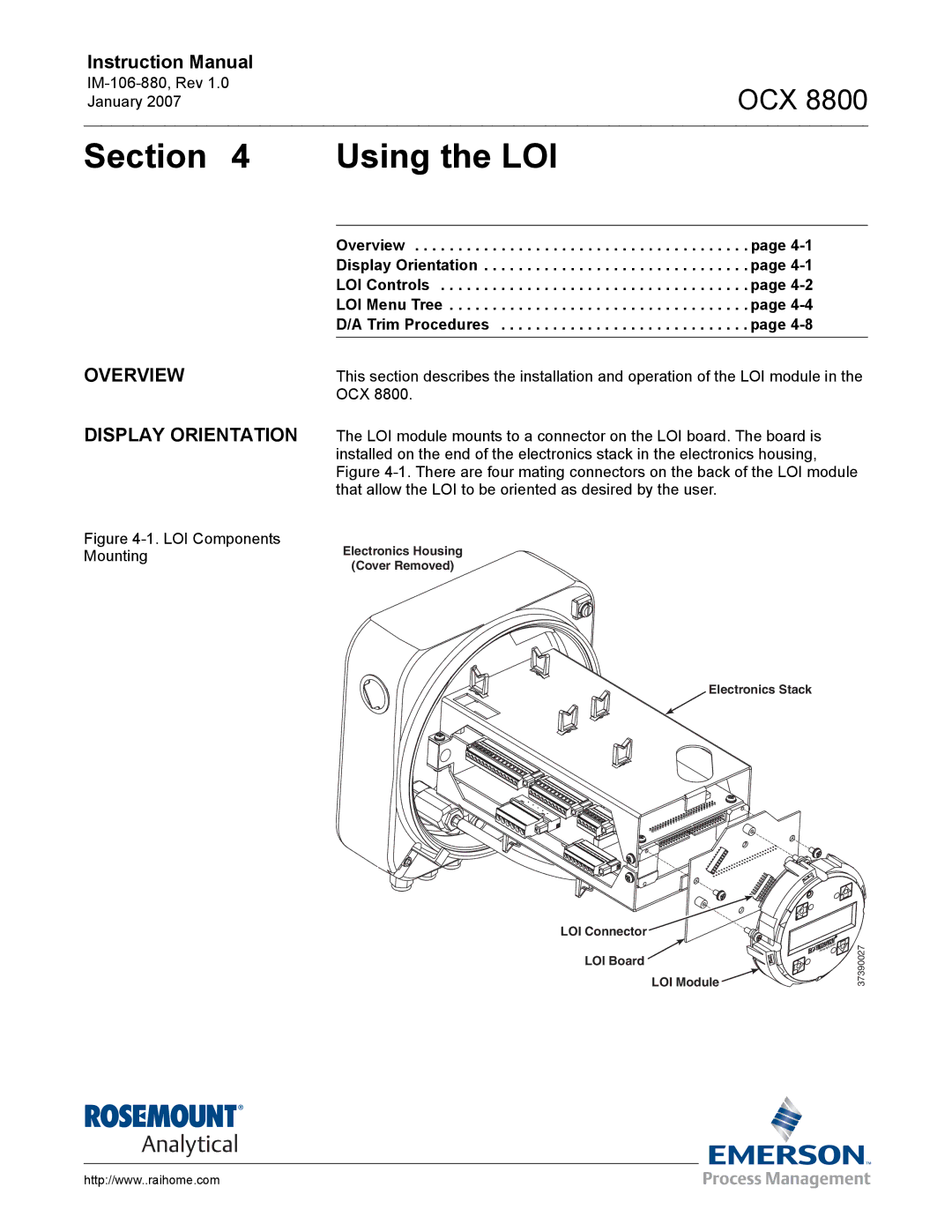
Overview Display Orientation
Section Using the LOI
LOI Key Functions
LOI Controls
Overview
Lockout
LOI Status Codes
First Column Submenus
LOI Menu Tree
Second Column Submenus
Third and Fourth Column Submenus
LOI Menu Tree Sheet 2
LOI Menu Tree Sheet 3
LOI Menu Tree Sheet 4
Trim Procedures O2 D/A trim procedure using the LOI
COe D/A trim procedure using the LOI
OCX
Overview Hart Communicator Signal Connections
Using Hart Communications
Method 1, for Load Resistance ≥ 250 Ohms
Signal Line Connections ≥ 250 Ohms Load Resistance
OUT
Method 2, for Load Resistance 250 Ohms
Off-line and On-line Operations
Hart Communicator PC Connections
Is specific to OCX 8800 applications
Hart Menu Tree
Hart Menu Tree Sheet 2 IM-106-880, Rev 1.0 January
Hart Menu Tree Sheet 3
Hart Menu Tree Sheet 4
Trim Procedures O2 D/A trim procedure using HART/AMS
COe D/A trim procedure using HART/AMS
Overview Fully Automatic Calibration
Autocalibration Setup using the LOI
Section Calibration
COE Calib Params
Autocalibration Setup using Hart
OCX
Autocalibration using Hart
Autocalibration using the LOI
Manual Calibration using the LOI
Operator Initiated Autocalibration Manual Calibration
Manual O2 Calibration using Hart
OCX
Manual COe Calibration using Hart
Manual O2 and COe Calibration using Hart
OCX
OCX
Overview
Maintenance and Service
OCX 8800 Removal and Installation
Remove OCX
OCX with Integral Electronics
Electronics Housing Terminal Blocks
Install OCX
Remove Cover and Terminals Insulator
Repair Sensor Housing
Sensor Housing Disassembly
Removal of O2 Cell Heater Strut Assembly
Remove Sample Block Heater Rods
Remove O2 Cell and Heater Strut Assembly
COe Sensor Thermocouple, and Heater Connections
Remove COe Sensor Assembly
Removal COe Sensor Assembly
Alignment COe Sensor Assembly
Eductor Alignment Matchmarks
Remove Eductor
Sensor Housing Sample Tube Exhaust Tube Situ Filter
10. O2 Cell, Heater Thermocouple, Exploded View
Disassemble O2 Cell and Heater Strut Assembly
11. COe Sensor Exploded View
Disassemble COe Sensor Assembly
Assemble COe Sensor Assembly
Sensor Housing Assembly
Install Sample and Exhaust Tubes
Assemble O2 Sensor and Heater Strut Assembly
Install Eductor
14. COe Sensor Parts Alignment
15. Band Heater Height
Install COe Sensor Assembly
16. COe Sensor Holder Alignment
17. COe Sensor Thermocouple, and Heater Connections
Install Sample Block Heater Rods
18. Installation of O2 Cell Heater Strut Assembly
19. O2 Cell Thermocouple, Heater Connections
Sensor Housing Leak Test
Install O2 Cell and Heater Strut Assembly
Install Terminals Insulator and Cover
Electronics Housing Disassembly
Repair Electronics Housing
Remove Cover
Remove Flash Prom
Remove Electronics Stack
20. Removal/Installation of Electronics Housing Components
Remove EMI Filter and Terminal Block
Remove Solenoid Valves
Electronics Housing Assembly
Electronics Housing
TOP View
Install Cover
Remove Tube Fittings
Replace Tube Fittings
‘F’ Type Fitting
‘13’ Type Fitting
25. Removal Tube Fittings
Install Tube Fittings
Grounding Electrical Noise Electrostatic Discharge
Troubleshooting
Diagnostic Alarms
Total Power Loss
Probable Cause Recommended Corrective Action
Fault Isolation
SB Temp Hi Sample block heater temperature high, 190ºC
SB TC Open Sample block heater thermocouple open
Repair broken wire or loose connection
Oxygen Concentration %
Board Temp Hi Electronics temperature maximum exceeded, 85ºC
Htr Relay Failed Heater relay failure
Electronics Housing Sensor Housing
Alarm Relay Event Alarms/Conditions
OCX
O2 Cell and Heater Strut Assembly
Replacement Parts
Sensor Housing Components
Sensor Housing
Index No Part Number
37390088
Tube, Sample, 9 ft .7 m Inconel
Electronics Housing Components
Electronics Housing
LOI Module
EMI Filter and Terminal Block
O2 Cell and Heater Strut Assembly
OCX
Appendix a Safety Data
Safety Instructionsimportant
Důležité
Vigtigt
Belangrijk
OCX
Wichtig
Σημαντικο
Oluline Teave
Tärkeää
OCX
Fontos
Importante
Svarbu
Svarīgi
Importanti
Viktig
Ważne
Equipamento só pode ser aberto por técnicos qualificados
Dôležité
Pomembno
Importante
Viktigt
July 1
Safety Data Sheet for Ceramic Fiber Products
Threshold Limit Value See Section
Flash Point None
Exposure to Used Ceramic Fiber Product
Section VI. Reactivity Data STABILITY/CONDITIONS to Avoid
Ventilation
Concentration
High Pressure GAS Cylinders
OCX
Atex Clarification
OCX
Description
Appendix B SPA with Hart Alarm
B-1
B-2
DCS, PLC
Jumper and Switch Settings
Configuration/Calibration
Figure B-3. SPA Jumper Dip Switch Settings
Figure B-5. SPA Front Panel
OCX
Scle
Returning Material
Appendix C Return of Materials
OCX
Index
Symbols
RTD
Warranty
EUROPE, Middle EAST, Africa GAS Chromatography ASIA-PACIFIC