Manuals
/
Epson
/
Computer Equipment
/
All in One Printer
Epson
C40UX
service manual
Models:
C40UX
1
116
121
121
Download
121 pages
31.58 Kb
113
114
115
116
117
118
119
120
Troubleshooting
Specifications
Parts list
Error codes
Disassembling Flowchart
Errors
Delay of oparation
Disconnecting the FFC
Maintenance
Connector Summary
Page 116
Image 116
Page 115
Page 117
Page 116
Image 116
Page 115
Page 117
Contents
Stylus C40UX/C40SX/C20UX/C20SX
General Notice
Precautions
About This Manual
Revision Status
Contents
Adjustment
Disassembly
Product Description
Delay of oparation
Eeprom 29 H bit 0 value Model Delay time during printing
Differences between the Stylus C20 and the Stylus C40
Throughput
Horizontal Printable area Available dot CR Speed
Physical Specification
Printing Specification
Electrical specification
Paper Feeding
Input Data Buffer
Feed condition Time Speed
Safety Approvals
Envirormental Condition
Reliability
Acoustic Noise
Parallel Interface Forward Channel
Signal name In/Out Function description
USB Interface
Parameter
Parallel I/F mode Typical time of tack
Parameter Minimum Maximum
Pin No Signal Name ReturnG Functional description
Parallel Interface Reverse Channel
Prevention Hosts from Data Transfer Time-out
IEEE1284.4 Protocol
Operate Switch
Control Panel
Panel Functions
Printer Condition and Panel Status
Errors
Printer Initialization
Paper Specification
Paper Handling
Printing Area
Printable Area for Cut Sheet
Size
Paper LMLeft RMRight TMTop Black BM Color BM
Margin
Black Ink Cartridge
Color Ink Cartridge
Operating Principles
Overview
Printer Mechanism
Printhead
Printhead Sectional Drawing
Normal State
Ejecting State
Ink Path
Ink Cavity
Carriage Motor Specification
Items Specifications
Carriage Mechanism
Detection position
I/C change position
† PF motor drive transmission path
PF Motor Specifications
Paper Feeding Mechanism
† Switch the PF motor drive to ASF unit side
Paper Loading Mechanism ASF Unit
† Clutch Mechanism
ASF unit function & PF Motor rotational direction
† Transfer the PF motor drive to LD roller
11. Disengage & Clutch mechanism
† Paper Return Plate Pad holder
13. ASF Paper Loading Sequence
Ink System Mechanism
PF motor rotational direction & Ink System Mechanism
16. Cap Mechanism
Wiper with the cap unit
Non porous pad in cap
18. non porous pad in cap Stylus C40/C20
† Manual Cleaning
† Timer Cleaning
Ink Sequence
† Initial ink charge
† Flashing
Printing mode for Black mode
Printing mode
Printing mode for Color mode
Application of the DC Voltages
Electrical Circuit Operating Principles
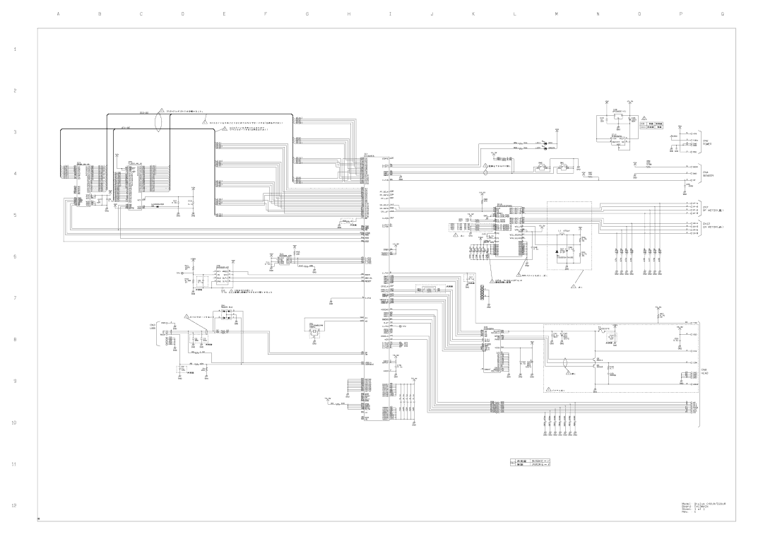
1 C417 PSB/PSE board
TRANST1
2 C413 MAIN/B Board
Main Elements
Troubleshooting
Motor Location Check Point Resistance
Sensor Name Check Point Signal Level Switch Mode
Sensor Check Point
Troubleshooting with LED Error Indications
Error Indicator of Operation Panel
Error Condition and possible cause
Printer Status Indicators Priority Power Error
Paper out error indication
Step Detail phenomenon Check point Remedy
Spur gear 35.2 is Rotating If it is no problem, proceed
Paper jam error indication
10. Paper jam error indication
11. Paper Jam Error indication
12. Ink Out error indication
Detail phenomenon Check point Remedy
14. Paper is always loaded without any print job
15. Fatal Error indication
13. Multiple papers are always loaded
17. Dot missing occur and it is not recovered with CL
18. Dot missing occur and it is not recovered with CL
19. Dot missing occur and it is not recovered with CL
20. Print quality is not good
21. Print quality is not good
22. Print quality is not good
Disassembly and Assembly
Precautions
Printer
Et que le cordon d’alimentation soit debranche
Name and Specification Outward Form
Tools
Screws
Name Supplier Parts No
Work Completion Check
Work Completion Check
Classifi Check Point Status Cation
Classifi Check Point Status
Disassembly
Disassembling Flowchart
Edge guide
Upper housing removal
Upper housing
ASF unit removal
CBP 3⋅ CBS P2 3⋅
Tube stopper Waste ink pad
„ Waste ink counter reset operation. Refer to Section
Waste ink pad removal
„ Tightening Torque for screw +/-1 kgf.cm
PS unit removal
CN2 PS unit S 3⋅ P 3⋅
Paper eject roller removal
Protrusion
CBS 3⋅
Front Frame
Paper Eject roller
Gear
USB Type CBS 3⋅ Parallel Type F.S-Tite 3⋅
Switch cover Hooks
Main board removal
21. Disconnecting the connectors
22. Removing the Main board
CR motor removal
Printhead unit removal
Carriage unit
Carriage cover
Printhead unit
30. Disconnecting the FFC
LD unit removal
LD unit Cables
Printer mechanism removal
Adjustment
Performance Priority
Required Adjustment
Required Adjustment
Adjustment Program Initial Setting menu
Main Menu Service
Adjustment Program feature
Basic adjustment items
Bi-d adjustment even if the paper is out in the ASF. When
Feed command until the paper is set in the ASF
Eeprom initial setting
Head ID
Read out the Head ID from the Eeprom
10. Choose the Bi-d adjustment
Bi-D
13. Bi-d adjustment input menu
USB ID
15. Choose the USB ID input menu
Top margin
16. Choose the Top margin menu
For the initial ink charge operation is so large
Head cleaning
Initial ink charge
Refurbishment for DOA
21. Choose the Refurbishment for DOA menu
Protection counter check
Check the present counter value
Clear the present counter value
Excepting ESP
Eepron check
26. Eeprom check function
29. Eeprom backup data
Eeprom back up data
15 A4 pattern will print
31. A4 Check pattern
32. A4 Check pattern
Maintenance
Cleaning
Service Maintenance
† Head Cleaning
† Maintenance Error Clear
Lubrication
Lubrication Type/Point Remarks
Lubrication Type/Point
Main frame Right side view
200mm
Appendix
Connector Summary
Major Component Unit
CN9-Printhead
Pin
Address Explanation Setting
Eeprom Address Map
Eeprom Address Map
Factory
Appendix Eeprom Address Map 103
Appendix Eeprom Address Map 104
Bit7 Bit6 Name mode
Market Eeprom address Eeprom setting
Bit3 Bit2 D4mode
Bit1 Bit0 D4mode
Component Layout
C413MAIN component layout
Appendix Component Layout 107
Ref No Description
Parts List
Parts list
Exploded Diagram
Stylus C40UX/C40SX/C20UX/C20SX Exploded Diagram
Appendix Exploded Diagram 110
Appendix Exploded Diagram 111
Stylus C40UX/C40SX/C20UX/C20SXRevision a
Appendix Exploded Diagram 113
Appendix Exploded Diagram 114
Electrical Circuits
Page
Page
Page
Page
Top
Page
Image
Contents