Fibre Channel I/O Blades | 4/4 Gbit FC Switch Blade SW4016 4D | |||||
Control and Connection Panel |
|
| ||||
3 | 4 | 5 | 6 | 7 | 8 | 9 |
21
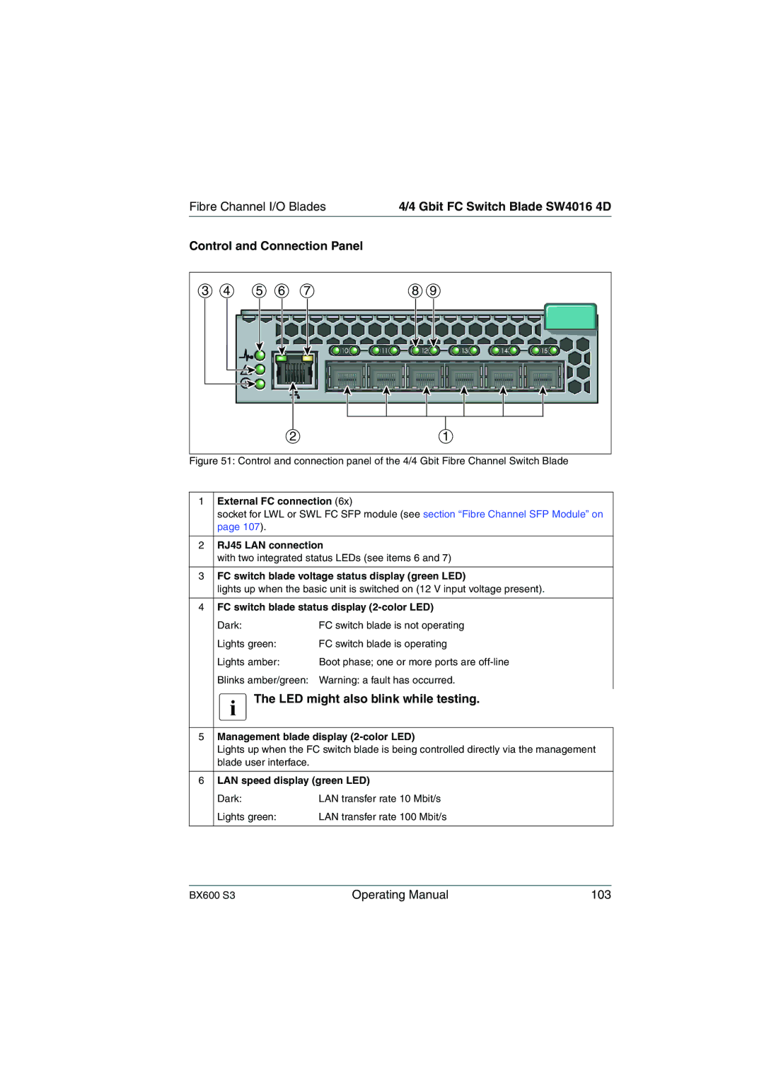
Figure 51: Control and connection panel of the 4/4 Gbit Fibre Channel Switch Blade
1 | External FC connection (6x) | |
| socket for LWL or SWL FC SFP module (see section “Fibre Channel SFP Module” on | |
| page 107). |
|
|
| |
2 | RJ45 LAN connection | |
| with two integrated status LEDs (see items 6 and 7) | |
|
| |
3 | FC switch blade voltage status display (green LED) | |
| lights up when the basic unit is switched on (12 V input voltage present). | |
|
| |
4 | FC switch blade status display | |
| Dark: | FC switch blade is not operating |
| Lights green: | FC switch blade is operating |
| Lights amber: | Boot phase; one or more ports are |
| Blinks amber/green: Warning: a fault has occurred. | |
| IThe LED might also blink while testing. | |
|
| |
5 | Management blade display | |
| Lights up when the FC switch blade is being controlled directly via the management | |
| blade user interface. |
|
6LAN speed display (green LED)
Dark: | LAN transfer rate 10 Mbit/s |
Lights green: | LAN transfer rate 100 Mbit/s |
BX600 S3 | Operating Manual | 103 |