Ethernet LAN | Ethernet I/O Blades |
8.8Ethernet LAN Pass-Thru-Blade
The Ethernet LAN
Control and Connection Panel
a b
9 | 7 | 5 | 3 | 1 |
10 | 8 | 6 | 4 | 2 |
a b
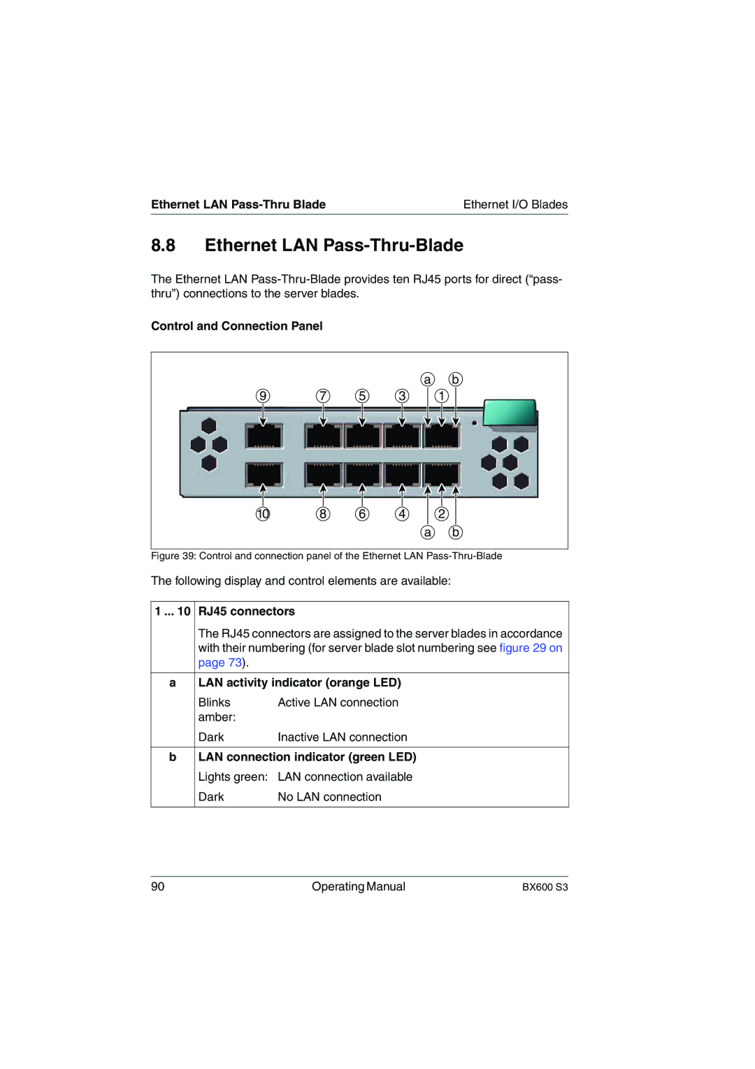
Figure 39: Control and connection panel of the Ethernet LAN Pass-Thru-Blade
The following display and control elements are available:
1 ... 10 | RJ45 connectors | |
| The RJ45 connectors are assigned to the server blades in accordance | |
| with their numbering (for server blade slot numbering see figure 29 on | |
| page 73). |
|
|
| |
a | LAN activity indicator (orange LED) | |
| Blinks | Active LAN connection |
| amber: |
|
| Dark | Inactive LAN connection |
|
| |
b | LAN connection indicator (green LED) | |
| Lights green: LAN connection available | |
| Dark | No LAN connection |
|
|
|
90 | Operating Manual | BX600 S3 |