4 Gbit FC | Fibre Channel I/O Blades |
Control and Connection Panel
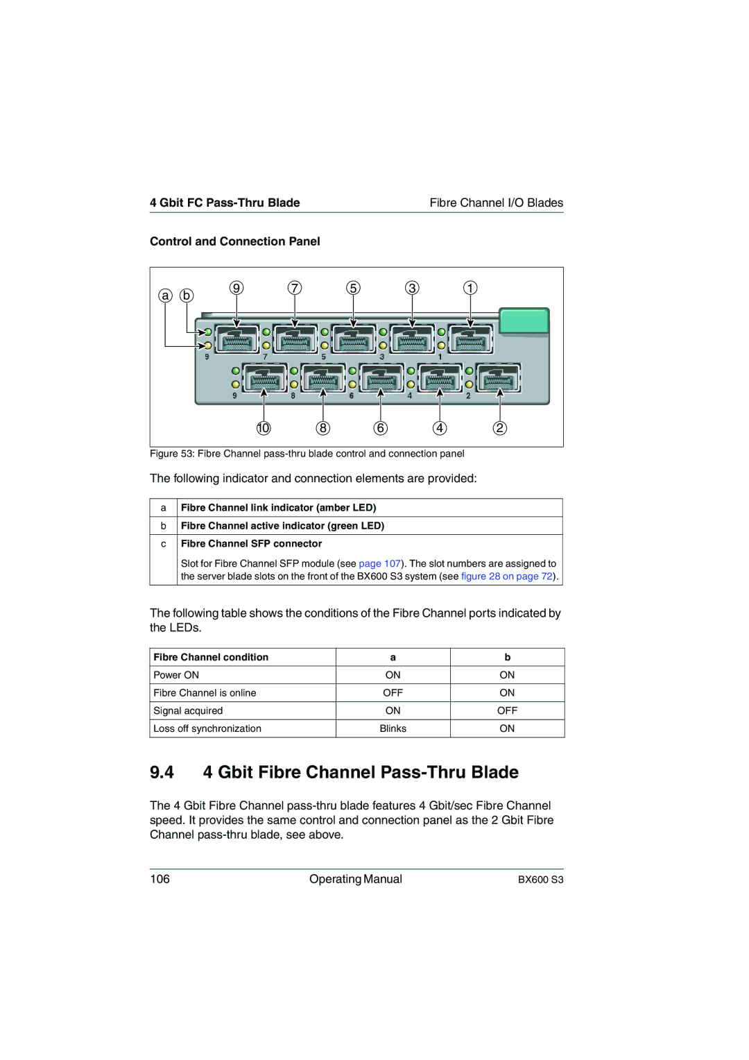
a b | 9 | 7 | 5 | 3 | 1 |
|
|
|
|
|
10 | 8 | 6 | 4 | 2 |
Figure 53: Fibre Channel pass-thru blade control and connection panel
The following indicator and connection elements are provided:
aFibre Channel link indicator (amber LED)
bFibre Channel active indicator (green LED)
cFibre Channel SFP connector
Slot for Fibre Channel SFP module (see page 107). The slot numbers are assigned to the server blade slots on the front of the BX600 S3 system (see figure 28 on page 72).
The following table shows the conditions of the Fibre Channel ports indicated by the LEDs.
Fibre Channel condition | a | b |
|
|
|
Power ON | ON | ON |
|
|
|
Fibre Channel is online | OFF | ON |
|
|
|
Signal acquired | ON | OFF |
|
|
|
Loss off synchronization | Blinks | ON |
|
|
|
9.44 Gbit Fibre Channel Pass-Thru Blade
The 4 Gbit Fibre Channel
106 | Operating Manual | BX600 S3 |