Ethernet I/O Blades | Port Assignment |
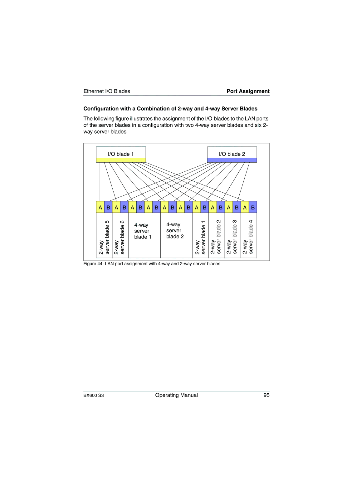
Configuration with a Combination of
The following figure illustrates the assignment of the I/O blades to the LAN ports of the server blades in a configuration with two
| I/O blade 1 |
|
|
|
| I/O blade 2 |
| ||||
A B A B A B A B A B A B A B A B A B A B | |||||||||||
| 5 |
| 6 |
| 1 |
| 2 | 3 |
| 4 | |
| blade |
| blade | blade |
| blade | blade |
| blade | ||
|
| server | server |
|
| ||||||
|
| blade 1 | blade 2 |
|
| ||||||
| server |
| server | server | server |
| server | ||||
| |||||||||||
Figure 44: LAN port assignment with 4-way and 2-way server blades
BX600 S3 | Operating Manual | 95 |