MultiLink ML1200 Managed Field Switch
GE Multilin
Electrical Safety requirements
Canadian Emissions Statement
Table of Contents
Access
10-1
10-3
10-5
10-13
10-7
10-12
10-19
15-4
14-9
15-1
15-5
18-1
17-14
17-16
18-3
Multilink ML1200 Managed Field Switch Introduction
Getting Started
Inspecting the Package and Product
Order Codes
ML1200
Specifications
Performance
Alarm Relay Contacts
Interrupts
Sinusoidal Vibration DNV To 4 G
North America CULus UL60950-1 C22.2 No
Applicable Council Directive According to
CE Compliance Low voltage directive EN60950-1 EMC Directive
ISO9001
Command Line Interface Firmware
Console Setup
Console Connection
Automatic IP Address Configuration
Console Screen
Logging In for the First Time
Setting the IP Parameters Using Console Port
Step
An example is shown below
Ipconfig ip=ip-address mask=subnet-mask dgw=gateway
ML1200# reboot
ML1200# save
Enable user-name
Privilege Levels
User Management
Command string TAB First character of the command TAB
Help command string
Command Enter
Help
Logout
Following example, the TAB key completes the command
Exiting
Following example illustrates logging out from a session
Make sure you use Https secure Http and not Http in the URL
Secure site will issue the certificate check shown below
EnerVista Secure Web Management
Example shown in the previous section, the URL is
Login screen
Select the Administration User Mgmt User Accounts menu item
To add a user, use the add button
Introduction
Introduction
Introduction
Modifying the Privilege Level
To exit or logout, click on the logout button
Confirm the logout by selecting OK in the pop-up window
Updating Multilink ML1200 Firmware
ML1200 Firmware Updates
Updating through the Command Line
Selecting the Proper Version
ML1200# xmodem get type=app
Https//IP address of the switch
Introduction
Introduction
Multilink ML1200 Managed Field Switch Product Description
Overview
Product Description
Product Description
PoE power pass-through, C2 Module MDIX, 10/100Mb 4-port
Four-Port Copper Module, C1 Module Mdix
Two-Port Fiber Modules, 2@ 100Mb fiber
Two -Port 10 Mb mm Fiber ST Modules
SFP Gigabit 1000Mbps port modules
Packet Prioritization, 802.1p QOS
Frame Buffering and Flow Control
Managed Network Firmware for Multilink ML1200-Series
Features Fiber-Built-In
Features and Benefits
Managed switching for high performance Ethernet LANs
Management Software included
Product Description
Applications
Example
Example
Multilink ML1200 Managed Field Switch Installation
Locating Multilink ML1200 Switches
Preparation
Connecting Ethernet Media
Fiber
Copper
Twisted Pair CAT 3, 4
Twisted Pair CAT
Gigabit SFP Small Form-factor Pluggable Optical Transceivers
H7 Module H8 HD Module
HE HJ Module
HK Module
Mechanical Installation
DIN-Rail Mounting the Multilink ML1200
Installation
Electrical Installation
Powering the Multilink ML1200 Managed Field Switch
3 ML1200 Port Module PM Installation
Transceiver Data
Pinout information for above connector
Request to Send
Ground
Multilink ML1200 Managed Field Switch Operation
Switching Functionality
Functionality
Status LEDs
Auto-Cross Mdix and Auto-negotiation, for RJ-45 ports
For Multilink ML1200 models /ML1200
Flow-control, Ieee 802.3x standard
Power Budget Calculations for ML1200 PM’s with Fiber Media
Typical
H4, HH Mb FX
Multilink ML1200 Managed Field Switch Port Modules
2 ML1200 Modules
2.2 C7 Module, 2@10Mb multi-mode FX-ST twist lock Module
CB Module, 2 Ports @100Mbps single-mode FX-SC-type, Sgl.M
CC Module, 4 @100Mb multi-mode FX , Mtrj Small-Form-factor
2.10 C1 Module Twisted Pair, 10/100Mb, 4-Port
PoE LEDs Summary
SFPs, Gigabit 1000Mbps port modules
Before Calling for Assistance
Operation
Multilink ML1200 Managed Field Switch IP Addressing
IP Address and System Information
Overview
Edit the IP address information
Configuring DHCP/bootp/Manual/AUTO
Dhcp and bootp
Bootp Database
Importance of an IP Address
Select the Administration System menu item
Click Edit
ML1200access## telnet enable
Using Telnet
Telnet enabledisable
ML1200access## exit ML1200#
Telnet ipaddress port=port number
Select the Administration Telnet menu item
Default port for telnet is
Show session Kill session id=session
For example
ML1200# show session
Setting Parameters
Setting Serial Port Parameters
System Parameters
Setvar sysnamesyscontactsyslocation =string
Date and Time
Snmp
Set timezone GMT=+ or hour=0-14 min=0-59
Network Time
Syntax for other date and time commands are
Following command sequence sets the daylight location
Set timeformat format=1224
ML1200sntp## sync hour=5 ML1200sntp## sntp enable
ML1200# sntp
ML1200sntp## exit
IP Addressing
IP Addressing
System Configuration
Saving and Loading Command Line
Config file
# Restricted Rights
System
Where module-name can be
Displaying configuration
Syntax show config module=module-name
Names, passwords
’show config’ command output
More
ML1200# show config module=snmp Hardware
Saving Configuration
Select Y. The ML1200 will prompt
Select N
Show host command displays the host table entries
Save format=v2v3
Script File
# Restricted Rights
Saving and Loading EnerVista Software
IP Addressing
Host Names
IP Addressing
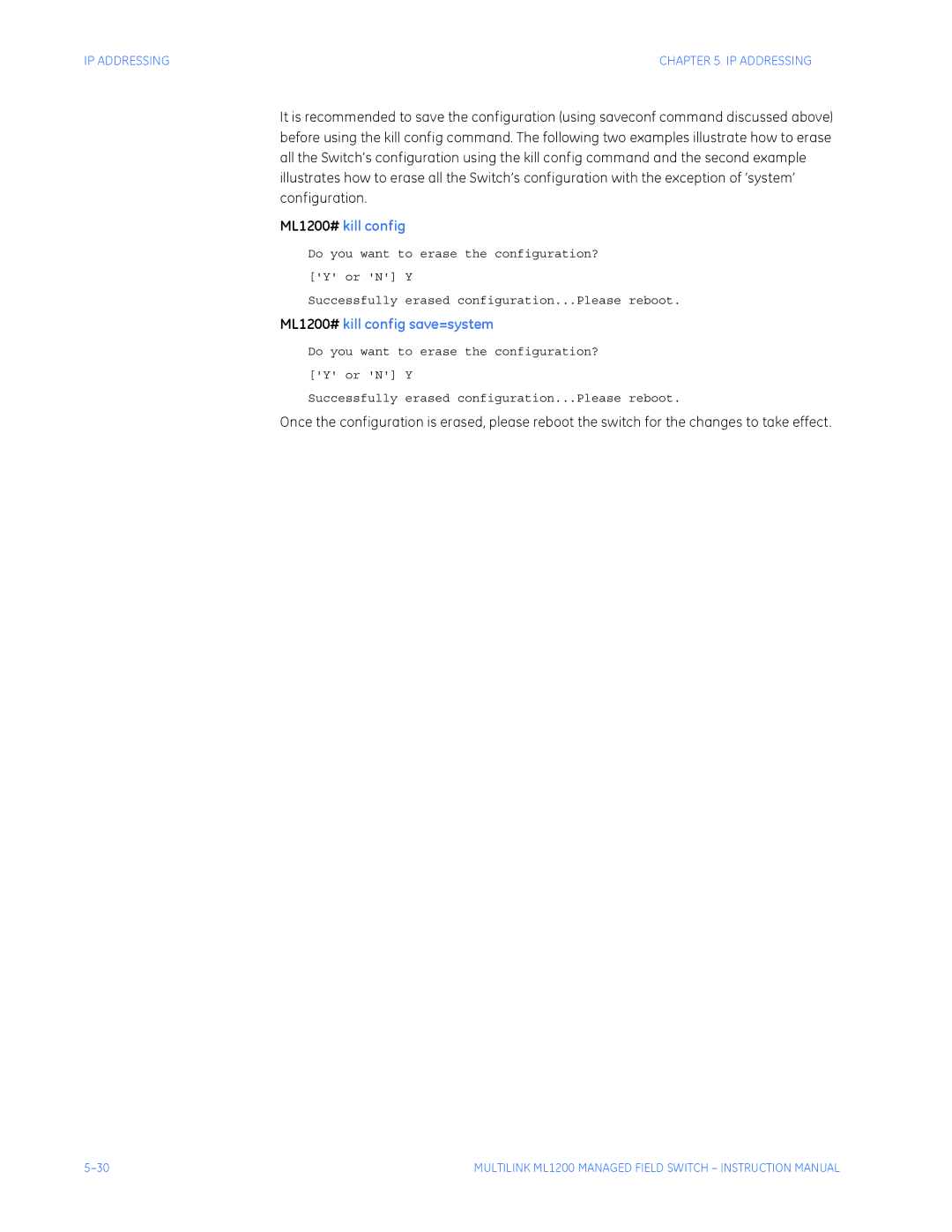
Erasing Configuration
Kill Config option using SWM
IP Addressing
IP-Access and Host Table settings
STP, Rstp settings
Port/Tag Vlan settings
Lacp settings
ML1200# kill config
IPv6
Introduction to IPv6
What’s changed in IPV6?
3 IPv6 Addressing
Syntax show ipv6 displays the IPv6 information
Configuring IPv6
Syntax ping6 IPv6 address pings an IPv6 station
Syntax ftp IPv6 address ftp to an IPv6 station
List of commands in this chapter
Syntax telnet IPv6 address telnet to an IPv6 station
Passwords
Multilink ML1200 Managed Field Switch Access Considerations
Securing Access
Description
Port Security Feature
Learn port=number-list enabledisable show port-security
Commands
For example, using the configure port-securitycommand
Ps enabledisable
Allowing MAC Addresses
ML1200port-security## ps enable
ML1200port-security## ps disable
ML1200port-security## allow
To deny a mac address, use the following
Example 6-1 Viewing the port security settings
ML1200port-security## learn port=3 enable
Example 6-2 Enabling learning on a port
Save the port-security configuration use the save command
ML1200port-security## signal port=3 logandtrap
Example 6-4 Removing MAC addresses from specific ports
Access Considerations
Example 6-5 Configuring port security
Security Logs
Example 6-6 Security log commands
Set logsize size=1-1000
ML1200# show log
Authorized Managers
Access
Show ip-access
Removeall
ML1200# access
ML1200access## exit
Example 6-7 Allowing/blocking specific IP addresses
Configuring Port Security with EnerVista Software
After enabling the EnerVista Secure Web Management software
Access Considerations
Access Considerations
Logs
Authorized Managers
Access Considerations
Access Considerations
Multilink ML1200 Managed Field Switch Access Using Radius
Introduction to
2 802.1x Protocol
802.1x network components
802.1x authentication details
Auth enabledisable
Configuring 802.1x through the Command Line Interface
Show auth configports
Auth
Show-statscommand displays 802.1x related statistics
Show-stats port=num
Trigger-reauthport=numlistrange
Example 7-1 Setting port control parameters
Example
On following
Setting port control parameters
ML1200auth## show-port backend
ML1200auth## shoW-port reauth
ML1200auth##
Commands
To edit the port settings, click on the edit icon
Select the Configuration Radius Port Access menu item
Access Using Radius
Access Using Radius
After all the port characteristics are enabled
Multilink ML1200 Managed Field Switch Access using TACACS+
Introduction to TACACS+
TACACS+ Flow
TACACS+ Packet
Packet type Possible values are
Tacacs packet format
Example 8-1 below, illustrates how to configure TACACS+
Configuring TACACS+ through the Command Line Interface
Tacplus enabledisable
Show tacplus statusservers
Example 8-1 Configuring TACACS+
ML1200user## tacplus enable
ML1200user## tacplus disable
Access Using TACACS+
Access Using TACACS+
Access Using TACACS+
Multilink ML1200 Managed Field Switch Port Mirroring Setup
Port Mirroring
Show port-mirror
Port Mirroring using the Command Line Interface
Prtmr enabledisable
Port-mirror
Setport command configures the port characteristics
Port Setup
Device command enters the device configuration mode
Device
ML1200device## show port
Example 9-1 Port setup
ML1200# device
ML1200device## exit ML1200#
Back Pressure
Where the rxthreshold value can be from 4 to 30 default is
Flow Control
Flowcontrol xonlimit=value xofflimit=value
Back pressure and flow control
ML1200device## show port=11
Broadcast Storms
Broadcast-protect enabledisable
Rate-thresholdport=portlistrange rate=frames/sec
Show broadcast-protect
Link Loss Alert
Example 9-3 Preventing broadcast storms
Example 9-4 Link loss alert
ML1200device## show port=3
Select the Configuration Port Mirroring menu item
Port Setup
Port Mirroring and Setup
Port Mirroring and Setup
Broadcast Storm menu
Port Mirroring and Setup
Multilink ML1200 Managed Field Switch Vlan
Vlan Description
Vlan
Multilink ML1200 supports up to 32 VLANs per switch
Tag Vlan vs. Port Vlan
10-4
Configuring Port VLANs through the Command Line Interface
Set vlan type=porttagnone
Add id=vlan Id name=vlan name port=numberlistrange
Edit id=vlan Id name=vlan name port=numberlistrange
Start vlan=namenumberlistrange
Save
Show vlan type=porttag id=vlanid
Vlan VID=1
Select the Configuration Vlan Port-Based menu item
Currently assigned Port VLANs are displayed as follows
10-9
10-10
10-11
Configuring Tag VLANs through the Command Line Interface
Show-port port=portlistrange
10-13
Example 10-1 Converting Port Vlan to Tag Vlan
Converting Port Vlan to Tag Vlan
ML1200tag-vlan##add id=20 name=marketing port=3-5
ML1200tag-vlan##set-port port=3-5 filter status=enable
Name engineering Status Active
Port Mode Status Tagged
10-19
Click On Configuration vlan tag-based Menu
Next step is to define the VLANs needed. To do that
10-21
Select the Configuration Vlan Tag-Based Tagging menu
10-23
10-24
Vlan Registration over Garp
Gvrp Concepts
Gvrp Operations
Vlan Registration Over Garp
Vlan assignment in Gvrp enabled switches
Port settings for Gvrp operations
Show-vlan
Static vlan=VID
ML1200# gvrp ML1200gvrp## show-vlan
Gvrp options
Example 11-1 Converting a dynamic Vlan to a static Vlan
ML1200gvrp## static vlan=10 ML1200gvrp## show-vlan
11-6
Show gvrp
Configuring Gvrp through the Command Line Interface
Gvrp Operation Notes
Show-forbid
Example 11-2 Configuring Gvrp
To configure Gvrp
Select the Configuration Vlan Gvrp menu item
Gvrp options on
11-10
Features and Operation
STP default values
Spanning Tree Protocol STP
Configuring STP
Show stp configports
Example 12-1 Viewing STP configuration
Example 12-2 Viewing STP ports
Set stp type=stprstp
Stp enabledisable
Stp
Show active-stp
Example 12-3shows how to enable STP using the above commands
Example 12-3 Enabling STP
Timers forward-delay=4-30 hello=1-10 age=6-40
Example 12-4 Configuring STP parameters
ML1200stp##show stp ports
Configuring STP parameters
ML1200stp##cost port=2 value=20
ML1200stp##port port=1 status=enable
Designated Root Priority 15535
Rstp concepts
Transition from STP to Rstp
Rapid Spanning Tree Protocol
13-3
Normal Rstp
Configuring Rstp through the Command Line Interface
Rstp enabledisable
Rstp
13-5
Example 13-2 Reviewing the Rstp port parameters
Path cost as defined in Ieee 802.1d / 802.1w
Forceversion stprstp
Show-forceversion
Show-timers
Port port=numberlistrange status=enabledisable
Example 13-4 Configuring Rstp
ML1200rstp##show stp config
Configuring Rstp
ML1200rstp##priority port=2 value=100
ML1200rstp##port port=1 status=disable
Syntax for the romode command on Rstp is shown below
Romode add port=portlistrange romode del port=portlistrange
Example 13-5 Configuring smart RSTP, ring-only mode
ML1200rstp##romode add port=1,2
13-15
Status Indicates whether STP or Rstp is enabled
13-17
Path cost defined in Ieee 802.1d and 802.1w
13-19
Click the Edit button to configure Rstp
Then Save Enable Status
13-22
Multilink ML1200 Managed Field Switch Quality of Service
QoS Overview
QoS Concepts
DiffServ and QoS
IP Precedence
IP Precedence ToS Field in an IP Packet Header
Show-portweight
Configuring QoS through the Command Line Interface
Set-weightweight=0-7
Qos
Show qos type=porttagtos port=portlistrange
Port weight settings
Show qos command displays the QoS settings
Set-untagport=portlistrange priority=highlow tag=0-7
Following example shows how to configure QoS
Example 14-1 Configuring QoS
Configuring QoS
ML1200qos##set-weight weight=4 ML1200qos##show-portweight
14-9
14-10
14-11
14-12
Multilink ML1200 Managed Field Switch Igmp
Igmp Concepts
Igmp
Figure below shows a network running Igmp
IP Multicast Filters
Isolating multicast traffic in a network
Reserved Addresses Excluded from IP Multicast Igmp Filtering
Igmp Support
Show igmp command displays the Igmp status
Configuring Igmp through the Command Line Interface
Igmp enable/disable
Igmp
Show-group
Show-port
Show-router
ML1200igmp## show-port
Following example shows how to configure Igmp
Example 15-1 Configuring Igmp
ML1200igmp## show-router
Configuring Igmp
ML1200igmp## mcast disable
ML1200igmp## mcast enable
15-11
15-12
Multilink ML1200 Managed Field Switch Snmp
Snmp Concepts
Snmp
Enterprise Traps Intruder
Traps
Standards
SNMPv1 standards
RFC 2271-2275 SNMPv3
Configuring Snmp through the Command Line Interface
Show-group id=id
Following example shows how to configure Snmp
Show-trap id=id#
Show-view id=id
Example 16-1 Configuring Snmp
Configuring Snmp
ML1200snmpv3## show-view
ML1200snmpv3## show-group
ML1200snmpv3## show-group id=1
ML1200snmpv3## show-view id=1
ML1200snmpv3## show-user
ML1200snmpv3## show-access
ML1200snmpv3## show-access id=1
ML1200snmpv3## show-user id=2
16-11
Multiple managers can be added as shown below
16-13
16-14
Configuring Rmon
Rmon
ML1200rmon## show rmon event
ML1200rmon## exit ML1200#
Multilink ML1200 Managed Field Switch Miscellaneous
Mail
Smtp enabledisable
Show smtp configrecipients
Smtp
Server command configures the global Smtp server settings
Delete id=1-5
Server ip=ip-addr port=1-65535 retry=0-3 domain=domain
ML1200smtp##show smtp config
Statistics
Following figure displays the port statistics for group
Serial Connectivity
Optimizing serial connection in HyperTerminal
History
Show history
Show version
Ping through the Command Line Interface
Ping
Ping through EnerVista Secure Web Management software
Changing the Command Line Prompt
Prompt
Set prompt prompt string
Following example illustrates a typical event log
Command Line Interface Example
System Events
Example 17-2 Typical system event log
Select the Configuration Statistics Log Statistics menu item
EnerVista Example
17-13
Command Reference
Main Commands
Set commands are listed below
Set password sets the current user password
Set timeout sets the system inactivity time out
Alarm commands are shown below
Configuration commands
Snmp enables or disables Snmp
Authorization commands are shown below
Device commands are shown below
Vlan Registration over Garp for details
Setqos configures QOS configuration usage
Rapid Spanning Tree Protocol for additional details
Passwd change the user password
Spanning Tree Protocol STP for additional details
17-20
Command Line Interface Settings
Multilink ML1200 Managed Field Switch Modbus Protocol
Modbus Configuration
Following command-line interface settings are available
ML1200# access ML1200access## modbus enable
ML1200access## show modbus
ML1200access## modbus port=602
EnerVista Settings
Select the Configuration Access Modbus menu item
Memory Mapping
Modbus Memory Map
Modbus memory map Sheet 1
Modbus memory map Sheet 2
Modbus memory map Sheet 3
Modbus memory map Sheet 4
Modbus memory map Sheet 5
Modbus memory map Sheet 6
Modbus memory map Sheet 7
Modbus memory map Sheet 8
Modbus memory map Sheet 9
Modbus memory map Sheet 10
Modbus memory map Sheet 11
Modbus memory map Sheet 12
Modbus memory map Sheet 13
Modbus memory map Sheet 14
Modbus memory map Sheet 15
Modbus memory map Sheet 16
Modbus memory map Sheet 17
Modbus memory map Sheet 18
Modbus memory map Sheet 19
Modbus memory map Sheet 20
Modbus memory map Sheet 21
Modbus memory map Sheet 22
Modbus memory map Sheet 23
Modbus memory map Sheet 24
Modbus memory map Sheet 25
Modbus memory map Sheet 26
Modbus memory map Sheet 27
Modbus memory map Sheet 28
Modbus memory map Sheet 29
Modbus memory map Sheet 30
Modbus memory map Sheet 31
Modbus memory map Sheet 32
Modbus memory map Sheet 33
Format Codes
18-38
Change Notes
Multilink ML1200 Managed Field Switch Appendix a
Revision History
Changes to the Manual
Warranty
GE Multilin Warranty Statement
Multilin
Power Consumption
48 V DC, 24 V DC and 125 V DC Power, Theory of Operation
Applications for DC Powered Ethernet Switches
ML1200, -48 V, 24 V, 125 V DC Installation
UL Requirements for DC-powered units
Operation
DC Power Input
Appendix C Internal DC Dual- Source Power Input
Specifications for Multilink ML1200 Field Switch
Power Supply Internal, -48VDC Dual-Source
Chapter C Internal DC DUAL-SOURCE Power Input Option
Dual-Source Option Theory of Operation
Features and Benefits of the Dual-Source Design
Installation