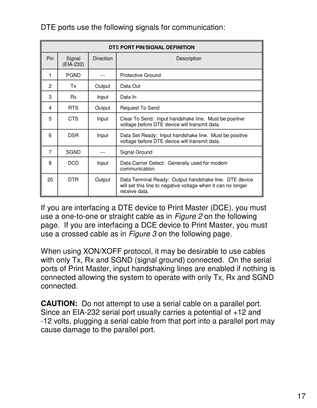
DTE ports use the following signals for communication:
DTE PORT PIN/SIGNAL DEFINITION
Pin | Signal | Direction | Description |
|
|
| |
1 | PGND | Protective Ground | |
|
|
|
|
2 | Tx | Output | Data Out |
|
|
|
|
3 | Rx | Input | Data In |
|
|
|
|
4 | RTS | Output | Request To Send |
|
|
|
|
5 | CTS | Input | Clear To Send: Input handshake line. Must be positive |
|
|
| voltage before DTE device will transmit data. |
|
|
|
|
6 | DSR | Input | Data Set Ready: Input handshake line. Must be positive |
|
|
| voltage before DTE device will transmit data. |
|
|
|
|
7 | SGND | Signal Ground | |
|
|
|
|
8 | DCD | Input | Data Carrier Detect: Generally used for modem |
|
|
| communication. |
|
|
|
|
20 | DTR | Output | Data Terminal Ready: Output handshake line. DTE device |
|
|
| will set this line to negative voltage when it can no longer |
|
|
| receive data. |
|
|
|
|
If you are interfacing a DTE device to Print Master (DCE), you must use a
When using XON/XOFF protocol, it may be desirable to use cables with only Tx, Rx and SGND (signal ground) connected. On the serial ports of Print Master, input handshaking lines are enabled if nothing is connected allowing the system to operate with only Tx, Rx and SGND connected.
CAUTION: Do not attempt to use a serial cable on a parallel port. Since an
17