6.Remove the Torx T15 screw that secures the assembly to the chassis. Figure
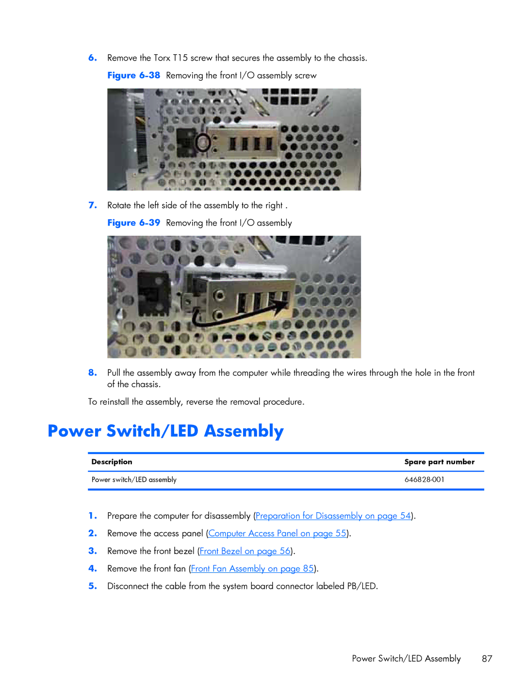
7.Rotate the left side of the assembly to the right . Figure
8.Pull the assembly away from the computer while threading the wires through the hole in the front of the chassis.
To reinstall the assembly, reverse the removal procedure.
Power Switch/LED Assembly
Description | Spare part number |
|
|
Power switch/LED assembly | |
|
|
1.Prepare the computer for disassembly (Preparation for Disassembly on page 54).
2.Remove the access panel (Computer Access Panel on page 55).
3.Remove the front bezel (Front Bezel on page 56).
4.Remove the front fan (Front Fan Assembly on page 85).
5.Disconnect the cable from the system board connector labeled PB/LED.
Power Switch/LED Assembly | 87 |