●Heat sink (Heat sink on page 139)
●Processor (Processor on page 141)
●WLAN module (WLAN module on page 113)
4.Remove the baffle from the chassis (Fan duct on page 132).
5.Remove the fan from the chassis (Front Fan Assembly on page 133).
6.Rotate the drive cage to its upright position.
7.Rotate the power supply to its full upright position.
8.Disconnect all data and power cables from the system board.
9.Disconnect the balance of the cables from the system board.
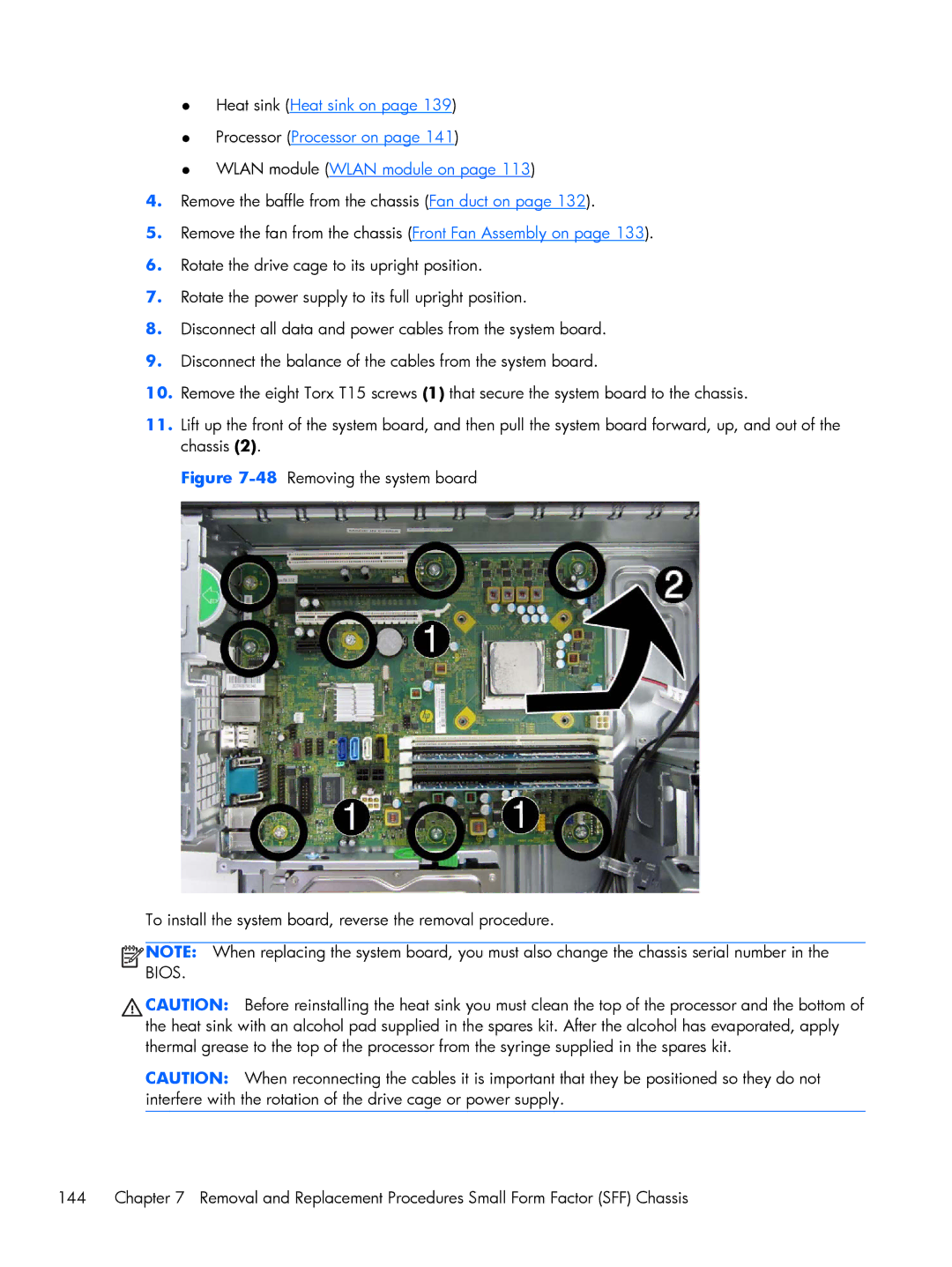
10.Remove the eight Torx T15 screws (1) that secure the system board to the chassis.
11.Lift up the front of the system board, and then pull the system board forward, up, and out of the chassis (2).
Figure 7-48 Removing the system board
To install the system board, reverse the removal procedure.
![]()
![]()
![]()
![]() NOTE: When replacing the system board, you must also change the chassis serial number in the BIOS.
NOTE: When replacing the system board, you must also change the chassis serial number in the BIOS.
CAUTION: Before reinstalling the heat sink you must clean the top of the processor and the bottom of the heat sink with an alcohol pad supplied in the spares kit. After the alcohol has evaporated, apply thermal grease to the top of the processor from the syringe supplied in the spares kit.
CAUTION: When reconnecting the cables it is important that they be positioned so they do not interfere with the rotation of the drive cage or power supply.
144 | Chapter 7 Removal and Replacement Procedures Small Form Factor (SFF) Chassis |