Designjet T2500 eMultifunction Series
Legal notices
Table of contents
Network configuration
103
121
136
140
151
166
172
182
200
201
220
226
230
236
239
247
250
Introduction
Safety precautions
Mains connection
Printer operation
Printer servicing
Using this guide
Use and maintenance
Troubleshooting
HP Start-Up Kit
Accessories, support and specifications
Printer models
Glossary
Index
Printer’s main features
Printer’s main features
Printer’s main components
Front view
Power switch Power socket
Rear view
Communication ports
Printer’s main components
Front panel
Left and right fixed icons
Home screen dynamic icons
Following items are displayed only on the home screen
Sleep mode
Information screen
To reach the information screen, press on the home screen
Information screen dynamic icons
Web Services
Printer software
Printer software
Turn the printer on and off
HP Designjet ePrint & Share
To turn it back on, use the power switch at the rear
Printer’s internal prints
Printer’s internal prints
Enww
Installing the software
Network configuration
Using IPv6
Connect the printer to your network
Using IPSec
Printer software installation
Connect a computer to the printer by network Windows
Your printer supports IPSec
Uninstall the printer software Windows
Open the Mac OS X HP Designjet Installer
Connect a computer to the printer by network Mac OS
Bonjour connection
TCP/IP connection
Click Continue
Uninstall the printer software Mac OS
Setting up the printer
Set up your Web-connected printer
Web Services manual configuration
Configure the printer’s Internet connection
Introduction
Configure firmware updates
Configure a scan-to-network or scan-to-FTP folder
Print quality Choose between Best, Normal, and Fast
Scan to network folder
Scan to FTP folder
Configure a scan-to-network or scan-to-FTP folder
Example Create a scan-to-network folder under Windows
Check the Share this folder box
Example Create a scan-to-network folder under Mac OS
Enww
Roll switching options
Preferences Paper options Roll switching options
Paper suitability options
Paper mismatch action
Turn nesting on and off
Nest options Wait time
Turn usage information on and off
Turn e-mail notifications on and off
Turn alerts on and off
Each case, you must set the following options
Control access to the printer
Front-panel security settings
To access alert settings under Windows
To access alert settings under Mac OS
Embedded Web Server security settings
Disable your HP ePrint Center connection
Require account ID
Set Windows driver preferences
Network configuration
Preconfigure network settings if required
Tools for preconfiguration
Verify correct operation
Troubleshooting
Add the printer to your network system
Reset network parameters
Link configuration methods
Enable or disable network protocols
Control network protocols
Front-panel menu items
Control network protocols
Dhcp Renew
Front-panel menu items
DHCPV6 Policy
Embedded services
Ipsec
Supported network protocols
TCP/IPv4
Personalizing the printer
Personalizing the printer
Access the HP Utility
Access the Embedded Web Server
Change the language of the front-panel display
Change the sleep mode setting
Change the auto-off setting
Change the loudspeaker volume
Change the language of the HP Utility
Configure network settings
Change the front-panel display brightness
Change the units of measurement
Change the graphic language setting
Network connectivity Gigabit Ethernet Modify configuration
Manage printer security
Select one of the following options
Change your printer’s email address
Paper handling
Paper handling
General advice
General advice
Load a roll onto the spindle
Open the roll cover
Enww
Load a roll onto the spindle
Load a roll into the printer
Load a roll into the printer
Is not in the list on
Quick procedure with paper on the roll
Front panel procedure with paper on the roll
Unload a roll
You may need to open the roll cover
Load a single sheet
Stacker
Manual printing with the stacker open
Enww
Paper presets
Basket
View information about the paper
Printing paper info
Move the paper
Maintain paper
Printing preferences Paper options Printing paper info
Press , then , then Setup Print retrieval Retrieval time
Change the drying time
Change the retrieval time
Turn the automatic cutter on and off
Feed and cut the paper
Working with two rolls
Uses of a multiroll printer
How the printer allocates jobs to paper rolls
Roll switching policy doesnt matter
Economically on
Printing
Print from a USB flash drive
Then , then Print from USB preferences
Print from a computer using a printer driver
Advanced print settings
Select print quality
Select paper size
Paper size can be specified in the following ways
Advanced print settings
Use the Windows printer driver
Use Windows forms
Select margins options
Print on loaded paper
Use the Mac OS X printer driver
Use the Embedded Web Server
Rescale a print
Change the treatment of overlapping lines
Preview a print
Print a draft
High-quality printing
You can specify high-quality printing in the following ways
Print in gray shades
Print with no margins
Print with crop lines
Use paper economically
Nest jobs to save roll paper
When does the printer try to nest pages?
Nesting on Paper saved by nesting
Use ink economically
Roll protection
Unattended printing/overnight printing
Paper options Roll protection
1Recommended settings for unattended printing
Print from iOS with AirPrint
Print from iOS with AirPrint
Scanning
Paper types suitable for scanning
Scan to file
Scan to file
Then Scan preferences
Preferences De-skew Off
Copying
Then Copy preferences
Web-connected printing
Web-connected printing
Enable Cloud printing for your printer
Print through the Cloud with HP Designjet ePrint & Share
Print by email
Print from a smartphone or tablet
Enww
View and print from the HP Designjet ePrint & Share website
Enww
Press the HP ePrint & Share icon
Scan to an email address
Sign in using your registered email address and password
Press the Scan icon on the front panels home screen
Enww
Enww
Share files in your Online Print History
Web-connected printing
Job queue management
103
Select when to print a job in the queue
Job queue in the front panel
Job queue
Job preview
Pause a job in the queue
Reprint a job from the queue
Save a scanned job to another destination
Delete a job from the queue
Job queue in the Embedded Web Server or HP Utility
Reprint or copy a job in the queue
Job status messages
Printing Drying Cutting paper Ejecting
Canceled The job has been canceled by the printer
Canceled by user
Printed
Empty job The job does not contain anything to print
Color management
Color management
How colors are represented
Summary of the color management process
Color calibration
Color management from printer drivers
Color management options
Printer emulation
Color adjustment options
You can adjust the colors of your print as follows
You can adjust the gray balance of your print under Windows
Printing in grayscale
Color management from printer drivers PostScript printers
HP Professional Pantone Emulation
Color emulation
Cmyk color emulation
Color management from the Embedded Web Server
Submit Job options
Color management from the front panel
Printing preferences Color options
Color management and the scanner
Practical printing examples
121
Print from Adobe Acrobat
Print from Adobe Acrobat
Print from Autodesk AutoCAD
Print from Autodesk AutoCAD
Enww
Using printer emulation
Using clip contents by margins
Print from Adobe Photoshop
Enww
Using PowerPoint
Print and scale from Microsoft Office
Enww
Using Project
Select File Page Setup Print
Practical printing examples
Using Excel
Enww
Enww
Retrieving printer usage information
Retrieving printer usage information
Get printer accounting information
Check usage statistics
Check usage statistics for a job
Set Send accounting files to Enabled
Request accounting data by email
Accounting statistics with the HP Utility
Accounting statistics with the Embedded Web Server
Request accounting data by email
Handling ink cartridges and printhead
Handling ink cartridges and printhead
HP Utility procedures
About the ink cartridges
Check the ink cartridges status
Remove an ink cartridge
Insert an ink cartridge
Insert an ink cartridge
Safe mode
About the printhead
Check the printhead status
Status, see Front-panel error messages on
Remove the printhead
Enww
Enww
Insert the printhead
Lift the printhead out of the carriage
Insert the printhead
Storage of anonymous usage information
Printer maintenance
151
Clean the exterior of the printer
Check printer status
Maintain the ink cartridges
Move or store the printer
Update the firmware
Automatic firmware updates
Manual firmware updates
Important notes
Update the software
Printer maintenance kits
Secure File Erase
Disk Wipe
Security
Scanner maintenance
Scanner maintenance
Clean the scanner’s glass plate
Enww
Clean the pressure rollers and the feed rollers
Replace the scanner’s glass plate
Replace the scanner’s glass plate
Enww
Enww
Enww
Calibrate the scanner
To calibrate the scanner
If calibration fails
Supplies and accessories
Supplies and accessories
How to order supplies and accessories
Order ink supplies
Order paper
Following ink supplies can be ordered for your printer
Roll paper
3Roll paper
Introduction to the accessories
Order accessories
PostScript Upgrade Spindle
Following accessories can be ordered for your printer
Spindle Adaptor Kit
Troubleshooting paper issues
Troubleshooting paper issues
Paper loading error messages
Paper cannot be loaded successfully
Unsuccessful roll load
Unsuccessful sheet load
Black ink is easily removed when touched
Paper type is not in the list
Transparent or translucent film
Photo paper
When is a job put on hold for paper?
Printer printed on the wrong paper type
An on hold for paper message
Paper has jammed in the print platen
Paper has jammed in the print platen
Enww
Enww
Paper has jammed in the stacker
Printer displays out of paper when paper is available
Printer reports unexpectedly that the stacker is full
Prints do not fall neatly into the basket
Print remains in the printer after printing has completed
Troubleshooting print-quality issues
Troubleshooting print-quality issues
183
Print-quality troubleshooting wizard
When you have any print-quality problem
Recalibrate the paper advance
Recalibrating the paper advance procedure
Return to default calibration
Horizontal lines across the image banding
Lines are too thick, too thin or missing
Lines appear stepped or jagged
Lines print double or in the wrong colors
Lines are discontinuous
Lines are blurred
Line lengths are inaccurate
Whole image is blurry or grainy
This problem can occur for several different reasons
Paper is not flat
Print is scuffed or scratched
Ink marks on the paper
Black ink comes off when you touch the print
Other smears on the paper
Edges of objects are stepped or not sharp
Edges of objects are darker than expected
Horizontal lines at the end of a cut sheet print
Vertical bands of different colors
White spots on the print
Colors are inaccurate
Colors are fading
Image is incomplete clipped at the bottom
Image is clipped
Image Diagnostics Print
Some objects are missing from the printed image
Image Diagnostics Print
If you still have a problem
Corrective action
Here is an example of the same printhead in a bad state
If you still have a problem
Troubleshooting scanner issues
Cannot access the network folder
Scanning to file is slow
Troubleshooting scan-quality issues
201
Troubleshooting scan-quality issues
Random vertical lines
Wrinkles or folds
Actions
Line discontinuities
Grain in area fills when scanning plain paper
Small color differences between adjacent CIS modules
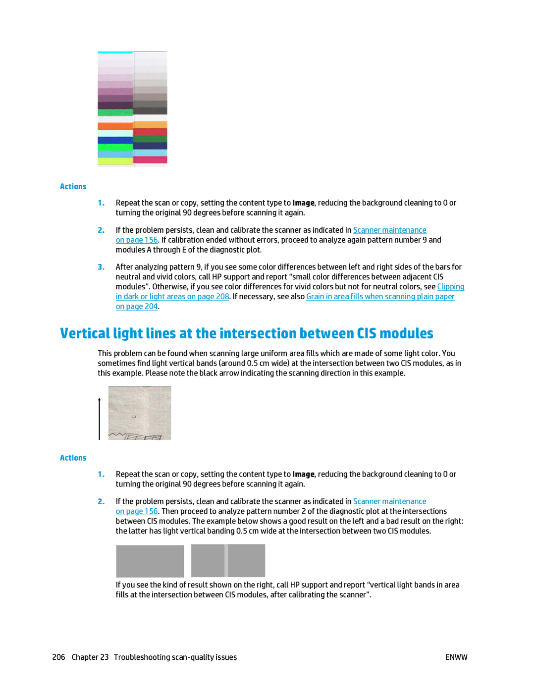
Vertical light lines at the intersection between CIS modules
Variable line thickness or missing lines
Inaccurately reproduced colors
Color fringing
Clipping in dark or light areas
Clipping in dark or light areas
Flare in the image when scanning glossy originals
Vertical red and green bands over white or black background
Stop-start effect
Vibration
Vibration
Horizontal periodical banding
Defocus, blurring and fading colors
Defocus, blurring and fading colors
Enww
Vertical black band 20 cm wide
Original Scan affected by a CIS failing module
Scanner damages some originals
Completely wrong colors
Vertical distortion
Object replication ghosting
Incorrect edge detection, mostly when scanning tracing paper
Copied or scanned image is very skewed
Scanner diagnostic plot
Scanner diagnostic plot
Visual check for errors while printing the diagnostic sheet
Resolution
Alignment
Maintenance Clean printheads
Loss of shadow or highlight details
Printer banding
Scan or copy the diagnostic plot
Streaks
Grain
Scan
Save the diagnostic plot for future use
Monitor calibration
Copy
Troubleshooting ink cartridge and printhead issues
Troubleshooting ink cartridge and printhead issues
Cannot insert an ink cartridge
Ink cartridge status messages
Cannot insert the printhead
Clean the printhead
Align the printhead
Printhead status messages
On page 145 and Insert the printhead on
Troubleshooting general printer issues
Troubleshooting general printer issues
Printer will not start
Printer does not print
Restore factory settings
Printer seems slow
Printer behaves strangely
Communication failures between computer and printer
Cannot access the HP Utility
Cannot access the Embedded Web Server
Cannot connect to the Internet
Web Services issues Automatic file system check
Alerts
All tests
Options on
Alerts
Front-panel error messages
Front-panel error messages
2Numerical error codes
237
System error log
Using a USB flash drive
Using the Embedded Web Server
HP Customer Care
239
Introduction HP Professional Services
HP Care Packs and Warranty Extensions
HP Support Center
HP Start-Up Kit
HP Installation
HP Proactive Support
Customer Self Repair
Convenient, easy to use
How to contact HP Support
Contact HP Support
Printer specifications
243
Functional specifications
Printer specifications
Physical specifications
Scanner resolutions 200, 300, 600 ppi
For a list of supported papers, see Order paper on
Memory specifications
Power specifications
Environmental specifications
Acoustic specifications
Glossary
Firmware
Gamut
Gigabit Ethernet
Hi-Speed USB
Paper
Platen
Printer driver
Printhead
Index
Paper size Print connectivity config
Usage 137 Reset paper advance
Specification 244 Speaker volume Status 141 Unit selection
Setup
Download presets Economical use
Paper not in list 174 Presets Print on loaded paper
170 Power On/off
229 Printhead cleaner
Clean glass plate 157
101 Network settings Sheet paper Load Sleep mode
Slow printing 232 Smartphone Software Software update 154
246 Printing resolutions Spindle