IBM System Storage DR550 |
|
|
|
|
| Version 3.0 |
|
|
|
|
|
|
|
|
|
|
|
| Page 34 | |||||||
|
|
|
|
|
|
|
|
|
|
|
|
|
|
|
|
|
|
|
|
|
|
|
|
|
|
|
d. Spacer |
|
|
|
|
|
|
|
|
|
|
|
|
|
|
|
|
|
|
|
|
|
|
| |||
|
|
|
|
|
|
|
|
|
|
|
|
|
|
|
|
|
|
|
|
|
|
|
|
|
|
|
|
|
|
|
| 1 |
|
|
|
|
|
|
|
|
|
|
|
|
|
|
|
|
|
|
| ||
|
|
|
|
|
|
|
|
|
|
|
|
|
|
|
|
|
|
|
|
|
|
|
|
|
| |
|
|
|
|
|
|
|
|
|
|
|
|
|
|
|
|
|
|
|
| 1 |
|
|
|
|
| |
|
|
|
|
| 2 |
|
| 1 Rack Chassis |
|
|
|
|
|
|
|
|
|
|
|
|
|
|
| |||
|
|
|
|
|
|
|
|
|
|
|
|
|
|
|
|
|
|
|
|
|
|
|
| |||
|
|
|
|
|
|
|
|
|
|
|
| 1 | T00 Rack Chassis | |||||||||||||
|
|
|
|
|
|
|
|
|
|
|
|
|
|
|
|
|
| |||||||||
|
|
|
|
|
|
|
|
|
|
|
|
|
|
| ||||||||||||
|
|
|
|
|
|
|
|
| 2 Top Trim Panel |
|
|
|
|
|
|
|
|
| ||||||||
|
|
|
|
|
|
|
|
|
|
|
|
|
|
|
|
|
| 2 | ||||||||
|
| 3 |
|
|
|
|
|
|
|
|
|
|
|
| ||||||||||||
|
|
|
|
|
|
|
| 3 Left Side Trim Panel |
|
|
|
|
|
|
|
|
| |||||||||
|
|
|
|
|
|
|
| 2 |
|
|
| |||||||||||||||
|
|
|
|
|
|
|
|
|
|
|
|
|
|
| 3 | Thin Washer | ||||||||||
|
|
|
|
|
|
|
|
| 4 Right Side Trim Panel |
|
|
|
|
|
| |||||||||||
|
|
|
|
|
|
|
|
|
|
|
|
|
|
|
|
|
| 4 | Top Plastic Isolator | |||||||
|
|
|
|
|
|
|
|
|
|
|
| |||||||||||||||
|
|
|
|
|
|
|
|
| 5 Spring Clip |
|
|
|
|
|
|
|
|
| ||||||||
|
|
|
|
|
|
|
|
|
|
|
| 3 |
|
|
|
|
|
|
|
|
| Bushing | ||||
|
|
|
|
|
|
|
|
|
|
|
|
|
|
|
|
|
|
|
|
|
| |||||
|
|
|
|
|
|
|
|
|
|
|
|
|
| 4 |
|
|
| 5 | Spacer | |||||||
|
|
|
|
|
|
|
|
|
|
|
|
|
|
|
|
| ||||||||||
|
|
|
|
|
|
|
|
|
|
|
|
|
|
|
|
| ||||||||||
|
|
|
|
|
|
|
|
|
|
|
|
|
|
|
| 6 | Jam Nut | |||||||||
|
|
|
|
|
|
|
|
|
|
|
| 667 | ||||||||||||||
|
|
|
|
|
|
|
|
|
|
|
| 7 | Leveling Foot | |||||||||||||
|
|
|
|
|
|
|
|
|
|
|
|
|
|
| 5 |
| ||||||||||
|
|
|
|
|
|
|
|
|
|
|
|
|
|
|
| |||||||||||
|
|
|
|
|
|
|
|
|
|
|
|
|
|
|
|
|
|
|
|
|
| |||||
|
|
|
| 4 |
|
|
|
|
|
|
|
|
|
|
|
|
|
|
|
|
|
|
| |||
|
|
|
|
|
|
|
|
|
|
|
|
|
|
|
|
|
|
|
|
|
|
|
|
|
| |
|
|
|
|
|
|
|
|
|
|
|
|
|
|
|
|
|
|
|
|
|
|
|
|
|
| |
|
|
|
|
|
|
|
|
|
|
|
|
|
|
|
|
|
|
|
| 6 |
|
|
|
| ||
|
|
|
|
|
|
|
|
|
|
|
|
|
|
|
|
|
|
|
|
|
|
|
|
| ||
|
|
|
|
|
|
|
|
|
|
|
|
|
|
|
|
|
|
|
|
|
|
|
|
|
| |
|
|
|
|
|
|
|
|
|
|
|
|
|
|
|
|
|
|
|
|
|
|
| ||||
|
|
|
|
|
|
|
|
|
|
|
|
|
|
|
|
|
|
|
| 7 |
|
|
| |||
|
|
|
|
|
|
|
|
|
|
|
|
|
|
|
|
|
|
|
|
|
|
|
|
|
|
|
|
|
|
|
|
|
|
|
|
|
|
|
|
|
|
|
|
|
|
|
|
|
|
|
|
|
|
|
|
|
|
|
|
|
|
|
|
|
|
|
|
|
|
|
|
|
|
|
|
|
| |||
|
|
|
|
|
| 5 |
|
|
|
|
|
|
|
|
|
|
|
|
|
|
|
|
|
| ||
|
|
|
|
|
|
|
|
|
|
|
|
|
|
|
|
|
|
|
|
|
|
|
|
|
|
|
|
|
|
|
|
|
|
|
|
|
|
|
|
|
|
|
|
|
|
|
|
|
|
|
|
|
|
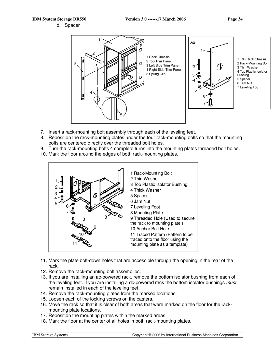
7.Insert a
8.Reposition the
9.Turn the
10.Mark the floor around the edges of both
|
|
|
|
|
|
|
|
|
|
|
|
|
|
|
| 1 | |
|
|
|
|
|
|
|
|
|
|
|
|
|
|
|
| 2 Thin Washer | |
| 1 |
|
|
|
|
|
|
|
|
|
|
|
|
| |||
|
|
|
|
|
|
|
|
|
|
|
|
|
| 3 | Top Plastic Isolator Bushing | ||
|
| 2 |
|
|
|
|
|
|
|
|
|
|
|
|
| ||
|
|
|
|
|
|
|
|
|
|
|
|
|
|
| |||
|
|
|
|
|
|
|
|
|
|
|
|
|
|
| |||
|
|
|
|
|
|
|
|
|
|
|
|
|
|
| 4 Thick Washer | ||
|
|
|
|
|
|
|
|
|
|
|
|
|
|
|
| ||
| 3 |
|
|
|
|
|
|
|
|
|
|
|
|
| |||
|
|
|
|
|
|
|
|
|
|
|
|
|
| 5 | Spacer | ||
| 4 |
|
|
|
|
|
|
|
|
|
|
|
|
| |||
|
|
|
|
|
|
|
|
|
|
|
|
|
| 6 Jam Nut | |||
| 5 |
|
|
|
|
|
|
|
|
|
|
|
|
| |||
|
|
|
|
|
|
|
|
|
|
|
|
|
| ||||
|
|
|
|
|
|
|
|
|
|
|
|
|
| ||||
|
|
|
| 6 |
|
|
|
|
|
|
|
|
| 7 | Leveling Foot | ||
|
|
|
|
|
|
|
|
|
|
|
|
|
| ||||
|
|
|
|
|
|
|
|
|
|
| |||||||
|
|
|
|
| 7 |
|
|
|
|
|
|
|
|
| 8 | Mounting Plate | |
|
|
|
|
|
|
|
|
|
|
|
|
|
|
| 8 | 9 | Threaded Hole (Used to secure |
|
|
|
|
| 144 | 8 |
|
| |||||||||
|
|
|
|
|
|
|
| ||||||||||
|
|
|
|
|
|
|
|
|
|
|
|
|
|
|
| the rack to mounting plate.) | |
|
|
|
|
|
|
|
|
|
|
|
|
|
|
|
| ||
|
|
|
|
|
|
|
|
|
|
|
|
| 9 |
|
| ||
|
|
|
|
|
|
|
|
|
|
|
|
|
|
| 10 Anchor Bolt Hole | ||
|
|
|
|
|
|
|
|
|
|
|
|
|
|
|
| ||
|
|
|
|
|
|
|
|
|
|
|
|
|
|
|
| ||
|
|
|
|
|
|
|
|
|
| 10 |
|
|
|
|
| 11 Traced Pattern (Pattern to be | |
|
|
|
|
|
|
|
|
|
|
|
|
|
|
|
| traced onto the floor using the | |
|
|
|
|
|
|
|
|
|
|
|
|
|
|
|
| ||
|
|
|
|
|
|
|
| 11 |
|
|
|
|
|
|
| ||
|
|
|
|
|
|
|
|
|
|
|
|
|
|
| mounting plate as a template) | ||
|
|
|
|
|
|
|
|
|
|
|
|
|
|
|
|
|
|
|
|
|
|
|
|
|
|
|
|
|
|
|
|
|
|
|
|
11.Mark the plate
12.Remove the
13.If you are installing an
14.Remove the
15.Loosen each of the locking screws on the casters.
16.Move the rack so that it is clear of both areas that were marked on the floor for the rack- mounting plate locations.
17.Reposition the mounting plates within the marked areas.
18.Mark the floor at the center of all holes in both
IBM Storage Systems | Copyright © 2006 by International Business Machines Corporation |
|
|