IBM System Storage DR550 | Version 3.0 | 17 March 2006 | Page 43 |
|
|
|
|
Dual Node Configurations
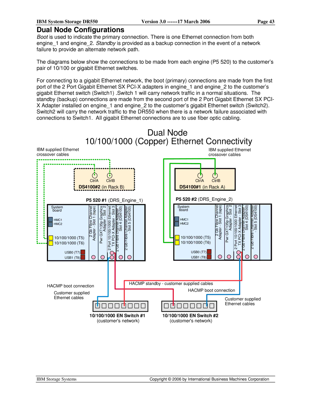
Boot is used to indicate the primary connection. There is one Ethernet connection from both engine_1 and engine_2. Standby is provided as a backup connection in the event of a network failure to provide an alternate network path.
The diagrams below show the connections to be made from each engine (P5 520) to the customer’s pair of 10/100 or gigabit Ethernet switches.
For connecting to a gigabit Ethernet network, the boot (primary) connections are made from the first port of the 2 Port Gigabit Ethernet SX
XAdapter installed on engine_1 and engine_2 to the customer’s gigabit Ethernet switch (Switch2). Switch2 will carry the network traffic to the DR550 when there is a network failure associated with connections to Switch1. All gigabit Ethernet connections are to use fiber optic cabling.
| Dual Node |
| 10/100/1000 (Copper) Ethernet Connectivity |
IBM supplied Ethernet | IBM supplied Ethernet |
crossover cables | crossover cables |
CtrlA CtrlB
DS4100#2 (in Rack B)
P5 520 #1 (DRS_Engine_1)
CtrlA CtrlB
DS4100#1 (in Rack A)
P5 520 #2 (DRS_Engine_2)
System |
| Channel | (tape)1 | ||
| board |
| |||
|
|
|
| ||
| HMC1 |
| Fibre Slot- | ||
|
| ||||
| HMC2 |
| |||
| |||||
|
|
|
| ||
| 10/100/1000 (T5) |
| 2 Gb | Adapter | |
| |||||
| 10/100/1000 (T6) |
|
|
| |
|
|
|
| ||
|
|
|
|
| |
| USB0 (T7) |
|
|
|
|
| USB1 (T8) |
|
|
|
|
|
|
|
|
| |
|
|
|
|
|
|
Pwr GXT135p Graphics Adapter - Slot 2
2 Port 10/100/1000 Ethernet TX
Channel Adapter | - Slot 5 (DS4100) |
2 Gb Fibre |
|
System board
![]()
![]() HMC1
HMC1
![]()
![]() HMC2
HMC2
![]()
![]() 10/100/1000 (T5)
10/100/1000 (T5) ![]()
![]() 10/100/1000 (T6)
10/100/1000 (T6)
USB0 (T7) ![]()
![]()
USB1 (T8) ![]()
![]()
Channel | 1 (tape) |
Fibre | - Slot |
2 Gb | Adapter |
|
|
GXT135p Graphics | Adapter - Slot 2 |
Pwr |
|
2 Port 10/100/1000 Ethernet TX
HACMP boot connection
Customer supplied Ethernet cables
HACMP standby - customer supplied cables
HACMP boot connection
Customer supplied
Ethernet cables
10/100/1000 EN Switch #1 | 10/100/1000 EN Switch #2 |
(customer's network) | (customer's network) |
IBM Storage Systems | Copyright © 2006 by International Business Machines Corporation |
|
|