IBM System Storage DR550 | Version 3.0 | 17 March 2006 | Page 32 |
|
|
|
|
Unpacking and Installing the Rack(s)
The DR550 comes integrated into one or two 7014 racks (single node configurations and the 5.6, 11.2, 22.4 and 44.8 TB dual node configurations are always shipped in one rack, while the dual node 89.6 TB configuration ships in two racks). Unpack Instructions are located in the transparent sleeve on the exterior of the rack shipping carton. This provides the information necessary to unpack and remove the rack(s) from the palette. Shipped with each DR550 is a printed copy of the 7014 Series Model T00 and Model T42 System Rack Installation Guide
Positioning the Rack
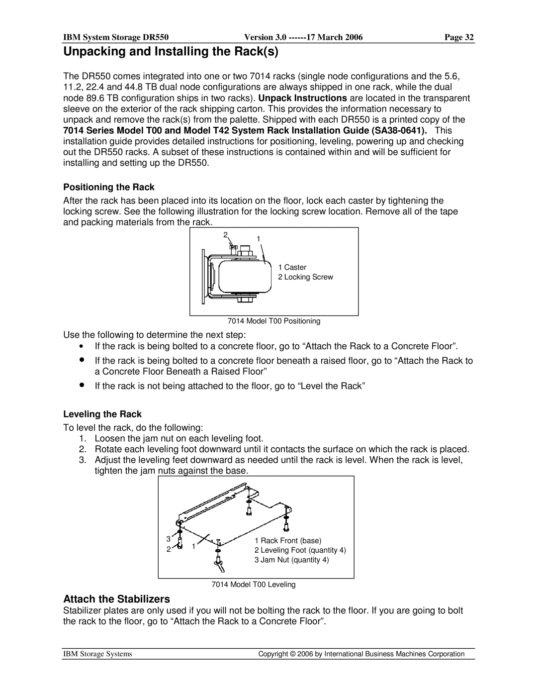
After the rack has been placed into its location on the floor, lock each caster by tightening the locking screw. See the following illustration for the locking screw location. Remove all of the tape and packing materials from the rack.
21
1 Caster
2 Locking Screw
7014 Model T00 Positioning
Use the following to determine the next step:
•If the rack is being bolted to a concrete floor, go to “Attach the Rack to a Concrete Floor”.
•If the rack is being bolted to a concrete floor beneath a raised floor, go to “Attach the Rack to a Concrete Floor Beneath a Raised Floor”
•If the rack is not being attached to the floor, go to “Level the Rack”
Leveling the Rack
To level the rack, do the following:
1.Loosen the jam nut on each leveling foot.
2.Rotate each leveling foot downward until it contacts the surface on which the rack is placed.
3.Adjust the leveling feet downward as needed until the rack is level. When the rack is level, tighten the jam nuts against the base.
3
2
1
1 Rack Front (base)
2 Leveling Foot (quantity 4)
3 Jam Nut (quantity 4)
7014 Model T00 Leveling
Attach the Stabilizers
Stabilizer plates are only used if you will not be bolting the rack to the floor. If you are going to bolt the rack to the floor, go to “Attach the Rack to a Concrete Floor”.
IBM Storage Systems | Copyright © 2006 by International Business Machines Corporation |
|
|
