Terminations |
|
|
| |
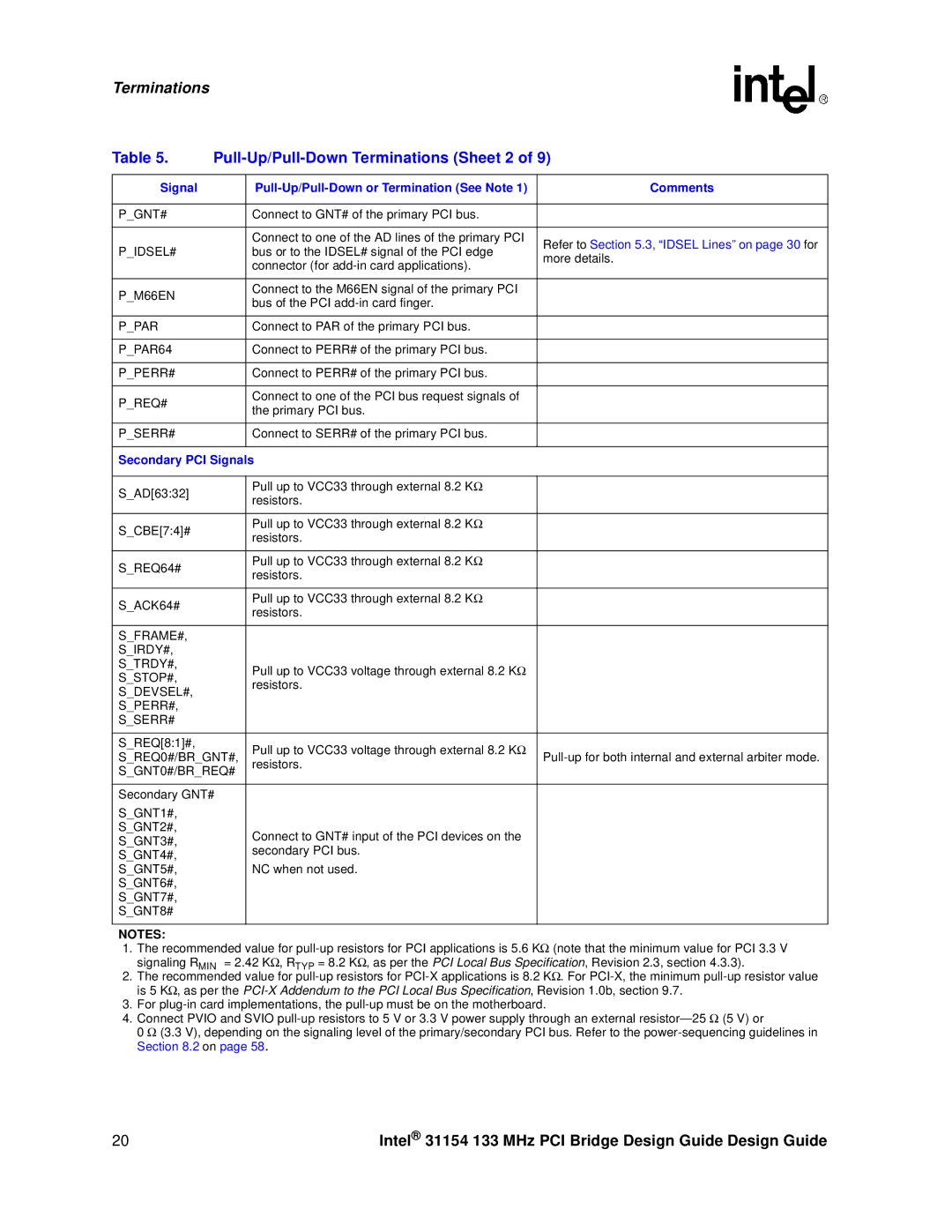
Table 5. |
| |||
|
|
|
| |
Signal |
| Comments | ||
|
|
|
| |
P_GNT# |
| Connect to GNT# of the primary PCI bus. |
| |
|
|
|
| |
|
| Connect to one of the AD lines of the primary PCI | Refer to Section 5.3, “IDSEL Lines” on page 30 for | |
P_IDSEL# |
| bus or to the IDSEL# signal of the PCI edge | ||
| more details. | |||
|
| connector (for | ||
|
|
| ||
|
|
|
| |
P_M66EN |
| Connect to the M66EN signal of the primary PCI |
| |
| bus of the PCI |
| ||
|
|
| ||
|
|
|
| |
P_PAR |
| Connect to PAR of the primary PCI bus. |
| |
|
|
|
| |
P_PAR64 |
| Connect to PERR# of the primary PCI bus. |
| |
|
|
|
| |
P_PERR# |
| Connect to PERR# of the primary PCI bus. |
| |
|
|
|
| |
P_REQ# |
| Connect to one of the PCI bus request signals of |
| |
| the primary PCI bus. |
| ||
|
|
| ||
|
|
|
| |
P_SERR# |
| Connect to SERR# of the primary PCI bus. |
| |
|
|
| ||
Secondary PCI Signals |
| |||
|
|
|
| |
S_AD[63:32] |
| Pull up to VCC33 through external 8.2 KΩ |
| |
| resistors. |
| ||
|
|
| ||
|
|
|
| |
S_CBE[7:4]# |
| Pull up to VCC33 through external 8.2 KΩ |
| |
| resistors. |
| ||
|
|
| ||
|
|
|
| |
S_REQ64# |
| Pull up to VCC33 through external 8.2 KΩ |
| |
| resistors. |
| ||
|
|
| ||
|
|
|
| |
S_ACK64# |
| Pull up to VCC33 through external 8.2 KΩ |
| |
| resistors. |
| ||
|
|
| ||
|
|
|
| |
S_FRAME#, |
|
|
| |
S_IRDY#, |
|
|
| |
S_TRDY#, |
| Pull up to VCC33 voltage through external 8.2 KΩ |
| |
S_STOP#, |
|
| ||
| resistors. |
| ||
S_DEVSEL#, |
|
| ||
|
|
| ||
S_PERR#, |
|
|
| |
S_SERR# |
|
|
| |
|
|
|
| |
S_REQ[8:1]#, |
| Pull up to VCC33 voltage through external 8.2 KΩ |
| |
S_REQ0#/BR_GNT#, | ||||
resistors. | ||||
S_GNT0#/BR_REQ# |
| |||
|
| |||
|
|
| ||
Secondary GNT# |
|
| ||
S_GNT1#, |
|
|
| |
S_GNT2#, |
| Connect to GNT# input of the PCI devices on the |
| |
S_GNT3#, |
|
| ||
| secondary PCI bus. |
| ||
S_GNT4#, |
|
| ||
|
|
| ||
S_GNT5#, |
| NC when not used. |
| |
S_GNT6#, |
|
|
| |
S_GNT7#, |
|
|
| |
S_GNT8# |
|
|
| |
|
|
|
| |
NOTES:
1.The recommended value for
2.The recommended value for
3.For
4.Connect PVIO and SVIO
0 Ω (3.3 V), depending on the signaling level of the primary/secondary PCI bus. Refer to the
20 | Intel® 31154 133 MHz PCI Bridge Design Guide Design Guide |
