Terminations |
|
|
|
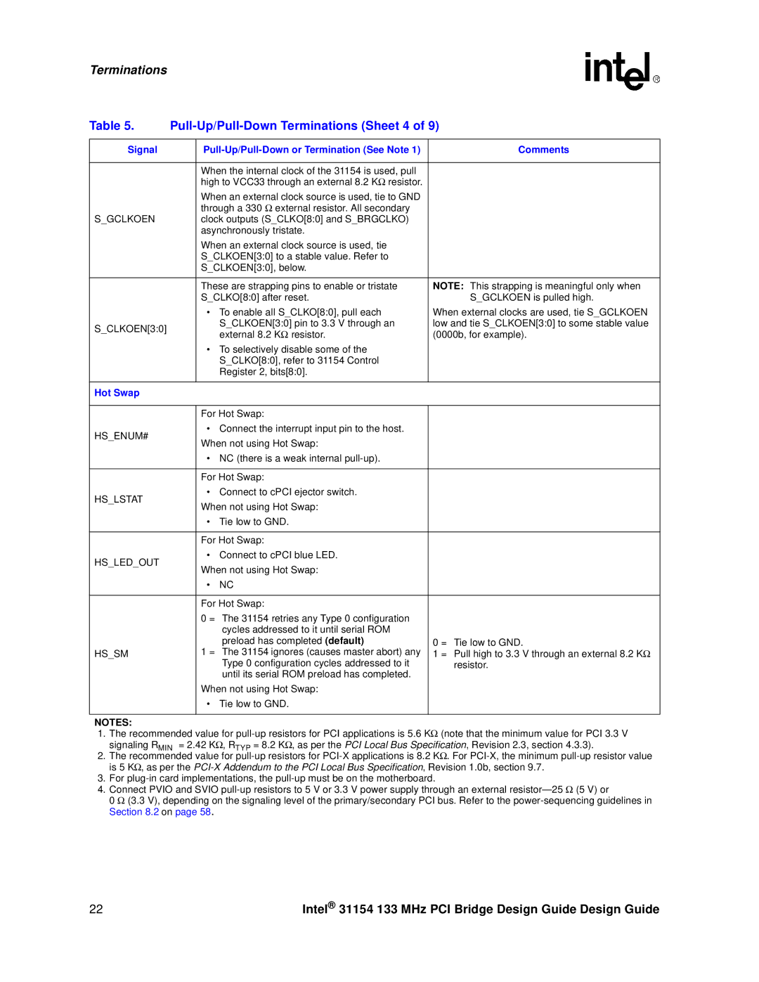
Table 5. |
| ||
|
|
|
|
Signal |
| Comments | |
|
|
|
|
|
| When the internal clock of the 31154 is used, pull |
|
|
| high to VCC33 through an external 8.2 KΩ resistor. |
|
|
| When an external clock source is used, tie to GND |
|
|
| through a 330 Ω external resistor. All secondary |
|
S_GCLKOEN |
| clock outputs (S_CLKO[8:0] and S_BRGCLKO) |
|
|
| asynchronously tristate. |
|
|
| When an external clock source is used, tie |
|
|
| S_CLKOEN[3:0] to a stable value. Refer to |
|
|
| S_CLKOEN[3:0], below. |
|
|
|
|
|
|
| These are strapping pins to enable or tristate | NOTE: This strapping is meaningful only when |
|
| S_CLKO[8:0] after reset. | S_GCLKOEN is pulled high. |
|
| • To enable all S_CLKO[8:0], pull each | When external clocks are used, tie S_GCLKOEN |
S_CLKOEN[3:0] |
| S_CLKOEN[3:0] pin to 3.3 V through an | low and tie S_CLKOEN[3:0] to some stable value |
| external 8.2 KΩ resistor. | (0000b, for example). | |
|
| ||
|
| • To selectively disable some of the |
|
|
| S_CLKO[8:0], refer to 31154 Control |
|
|
| Register 2, bits[8:0]. |
|
|
|
|
|
Hot Swap |
|
|
|
|
|
|
|
|
| For Hot Swap: |
|
HS_ENUM# |
| • Connect the interrupt input pin to the host. |
|
| When not using Hot Swap: |
| |
|
|
| |
|
| • NC (there is a weak internal |
|
|
|
|
|
|
| For Hot Swap: |
|
HS_LSTAT |
| • Connect to cPCI ejector switch. |
|
| When not using Hot Swap: |
| |
|
|
| |
|
| • Tie low to GND. |
|
|
|
|
|
|
| For Hot Swap: |
|
HS_LED_OUT |
| • Connect to cPCI blue LED. |
|
| When not using Hot Swap: |
| |
|
|
| |
|
| • NC |
|
|
|
|
|
|
| For Hot Swap: |
|
|
| 0 = The 31154 retries any Type 0 configuration |
|
|
| cycles addressed to it until serial ROM |
|
|
| preload has completed (default) | 0 = Tie low to GND. |
HS_SM |
| 1 = The 31154 ignores (causes master abort) any | Ω |
| Type 0 configuration cycles addressed to it | 1 = Pull high to 3.3 V through an external 8.2 K | |
|
| resistor. | |
|
| until its serial ROM preload has completed. |
|
|
| When not using Hot Swap: |
|
|
| • Tie low to GND. |
|
|
|
|
|
NOTES:
1.The recommended value for
2.The recommended value for
3.For
4.Connect PVIO and SVIO
0 Ω (3.3 V), depending on the signaling level of the primary/secondary PCI bus. Refer to the
22 | Intel® 31154 133 MHz PCI Bridge Design Guide Design Guide |