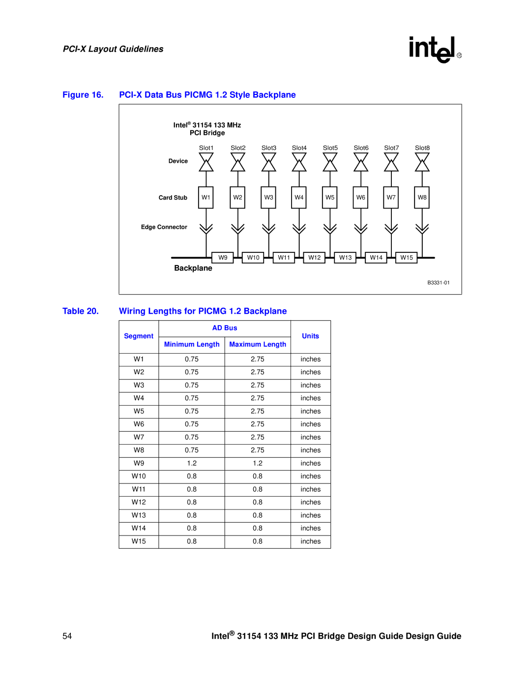
Figure 16. PCI-X Data Bus PICMG 1.2 Style Backplane
Intel® 31154 133 MHz |
|
|
|
|
|
| ||
| PCI Bridge |
|
|
|
|
|
|
|
| Slot1 | Slot2 | Slot3 | Slot4 | Slot5 | Slot6 | Slot7 | Slot8 |
Device |
|
|
|
|
|
|
|
|
Card Stub | W1 | W2 | W3 | W4 | W5 | W6 | W7 | W8 |
Edge Connector |
|
|
|
|
|
|
|
|
| W9 | W10 | W11 | W12 | W13 |
| W14 | W15 |
Backplane |
|
|
|
|
|
|
| |
|
|
|
|
|
|
|
| |
Table 20. Wiring Lengths for PICMG 1.2 Backplane
Segment | AD Bus | Units | |
|
| ||
| Minimum Length | Maximum Length |
|
|
|
|
|
W1 | 0.75 | 2.75 | inches |
|
|
|
|
W2 | 0.75 | 2.75 | inches |
|
|
|
|
W3 | 0.75 | 2.75 | inches |
|
|
|
|
W4 | 0.75 | 2.75 | inches |
|
|
|
|
W5 | 0.75 | 2.75 | inches |
|
|
|
|
W6 | 0.75 | 2.75 | inches |
|
|
|
|
W7 | 0.75 | 2.75 | inches |
|
|
|
|
W8 | 0.75 | 2.75 | inches |
|
|
|
|
W9 | 1.2 | 1.2 | inches |
|
|
|
|
W10 | 0.8 | 0.8 | inches |
|
|
|
|
W11 | 0.8 | 0.8 | inches |
|
|
|
|
W12 | 0.8 | 0.8 | inches |
|
|
|
|
W13 | 0.8 | 0.8 | inches |
|
|
|
|
W14 | 0.8 | 0.8 | inches |
|
|
|
|
W15 | 0.8 | 0.8 | inches |
|
|
|
|
54 | Intel® 31154 133 MHz PCI Bridge Design Guide Design Guide |
