|
|
| Terminations |
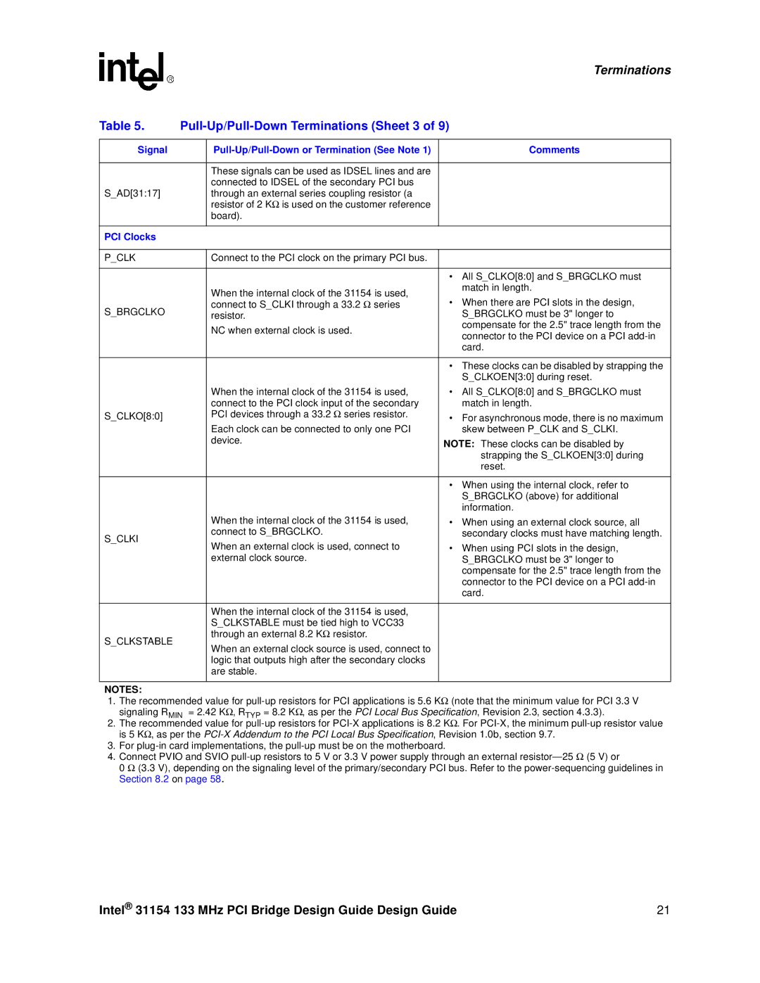
Table 5. |
| ||
|
|
|
|
Signal |
| Comments | |
|
|
|
|
|
| These signals can be used as IDSEL lines and are |
|
|
| connected to IDSEL of the secondary PCI bus |
|
S_AD[31:17] |
| through an external series coupling resistor (a |
|
|
| resistor of 2 KΩ is used on the customer reference |
|
|
| board). |
|
|
|
|
|
PCI Clocks |
|
|
|
|
|
|
|
P_CLK |
| Connect to the PCI clock on the primary PCI bus. |
|
|
|
|
|
|
|
| • All S_CLKO[8:0] and S_BRGCLKO must |
|
| When the internal clock of the 31154 is used, | match in length. |
|
| • When there are PCI slots in the design, | |
S_BRGCLKO |
| connect to S_CLKI through a 33.2 Ω series | |
| resistor. | S_BRGCLKO must be 3" longer to | |
|
| NC when external clock is used. | compensate for the 2.5" trace length from the |
|
| connector to the PCI device on a PCI | |
|
|
| |
|
|
| card. |
|
|
|
|
|
|
| • These clocks can be disabled by strapping the |
|
|
| S_CLKOEN[3:0] during reset. |
|
| When the internal clock of the 31154 is used, | • All S_CLKO[8:0] and S_BRGCLKO must |
|
| connect to the PCI clock input of the secondary | match in length. |
S_CLKO[8:0] |
| PCI devices through a 33.2 Ω series resistor. | • For asynchronous mode, there is no maximum |
|
| Each clock can be connected to only one PCI | skew between P_CLK and S_CLKI. |
|
| device. | NOTE: These clocks can be disabled by |
|
|
| |
|
|
| strapping the S_CLKOEN[3:0] during |
|
|
| reset. |
|
|
|
|
|
|
| • When using the internal clock, refer to |
|
|
| S_BRGCLKO (above) for additional |
|
|
| information. |
|
| When the internal clock of the 31154 is used, | • When using an external clock source, all |
S_CLKI |
| connect to S_BRGCLKO. | secondary clocks must have matching length. |
| When an external clock is used, connect to | • When using PCI slots in the design, | |
|
| ||
|
| external clock source. | S_BRGCLKO must be 3" longer to |
|
|
| compensate for the 2.5" trace length from the |
|
|
| connector to the PCI device on a PCI |
|
|
| card. |
|
|
|
|
|
| When the internal clock of the 31154 is used, |
|
|
| S_CLKSTABLE must be tied high to VCC33 |
|
S_CLKSTABLE |
| through an external 8.2 KΩ resistor. |
|
| When an external clock source is used, connect to |
| |
|
|
| |
|
| logic that outputs high after the secondary clocks |
|
|
| are stable. |
|
|
|
|
|
NOTES:
1.The recommended value for
2.The recommended value for
3.For
4.Connect PVIO and SVIO
0 Ω (3.3 V), depending on the signaling level of the primary/secondary PCI bus. Refer to the
Intel® 31154 133 MHz PCI Bridge Design Guide Design Guide | 21 |