|
|
| Terminations |
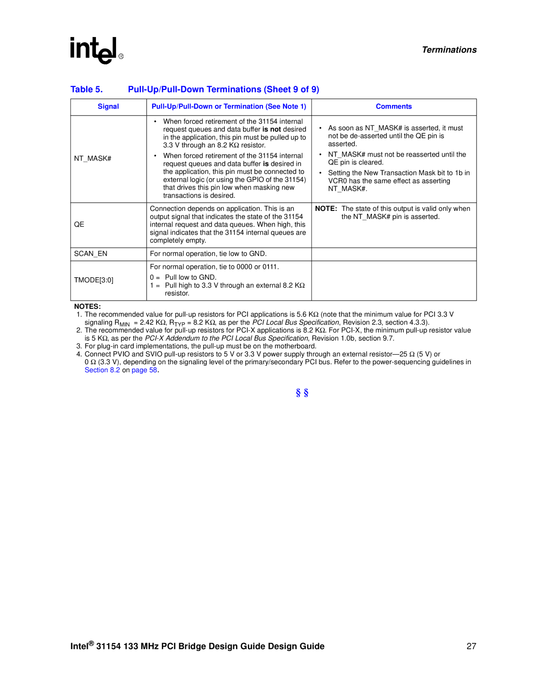
Table 5. |
| ||
|
|
|
|
Signal |
| Comments | |
|
|
|
|
|
| • When forced retirement of the 31154 internal | • As soon as NT_MASK# is asserted, it must |
|
| request queues and data buffer is not desired | |
|
| in the application, this pin must be pulled up to | not be |
|
| 3.3 V through an 8.2 KΩ resistor. | asserted. |
NT_MASK# |
| • When forced retirement of the 31154 internal | • NT_MASK# must not be reasserted until the |
| request queues and data buffer is desired in | QE pin is cleared. | |
|
| ||
|
| the application, this pin must be connected to | • Setting the New Transaction Mask bit to 1b in |
|
| external logic (or using the GPIO of the 31154) | VCR0 has the same effect as asserting |
|
| that drives this pin low when masking new | NT_MASK#. |
|
| transactions is desired. |
|
|
|
|
|
|
| Connection depends on application. This is an | NOTE: The state of this output is valid only when |
|
| output signal that indicates the state of the 31154 | the NT_MASK# pin is asserted. |
QE |
| internal request and data queues. When high, this |
|
|
| signal indicates that the 31154 internal queues are |
|
|
| completely empty. |
|
|
|
|
|
SCAN_EN |
| For normal operation, tie low to GND. |
|
|
|
|
|
|
| For normal operation, tie to 0000 or 0111. |
|
TMODE[3:0] |
| 0 = Pull low to GND. |
|
| 1 = Pull high to 3.3 V through an external 8.2 KΩ |
| |
|
|
| |
|
| resistor. |
|
|
|
|
|
NOTES:
1.The recommended value for
2.The recommended value for
3.For
4.Connect PVIO and SVIO
0 Ω (3.3 V), depending on the signaling level of the primary/secondary PCI bus. Refer to the
§§
Intel® 31154 133 MHz PCI Bridge Design Guide Design Guide | 27 |
