Terminations |
|
|
|
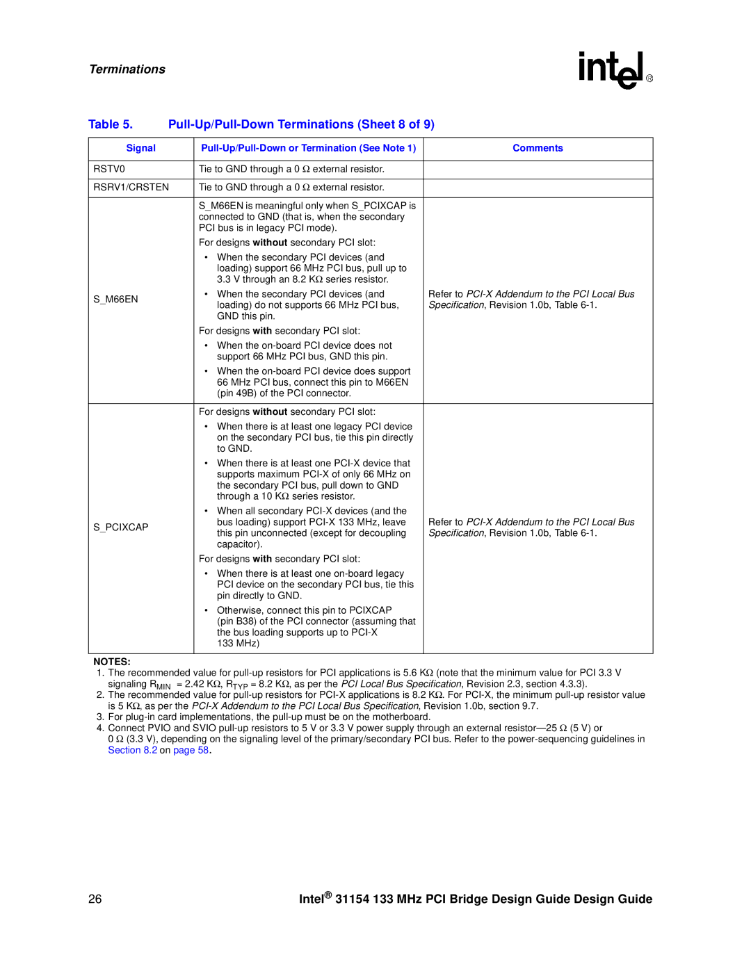
Table 5. |
| ||
|
|
|
|
Signal |
| Comments | |
|
|
|
|
RSTV0 |
| Tie to GND through a 0 Ω external resistor. |
|
|
|
| |
RSRV1/CRSTEN | Tie to GND through a 0 Ω external resistor. |
| |
|
|
|
|
|
| S_M66EN is meaningful only when S_PCIXCAP is |
|
|
| connected to GND (that is, when the secondary |
|
|
| PCI bus is in legacy PCI mode). |
|
|
| For designs without secondary PCI slot: |
|
|
| • When the secondary PCI devices (and |
|
|
| loading) support 66 MHz PCI bus, pull up to |
|
|
| 3.3 V through an 8.2 KΩ series resistor. |
|
S_M66EN |
| • When the secondary PCI devices (and | Refer to |
| loading) do not supports 66 MHz PCI bus, | Specification, Revision 1.0b, Table | |
|
| ||
|
| GND this pin. |
|
|
| For designs with secondary PCI slot: |
|
|
| • When the |
|
|
| support 66 MHz PCI bus, GND this pin. |
|
|
| • When the |
|
|
| 66 MHz PCI bus, connect this pin to M66EN |
|
|
| (pin 49B) of the PCI connector. |
|
|
|
|
|
|
| For designs without secondary PCI slot: |
|
|
| • When there is at least one legacy PCI device |
|
|
| on the secondary PCI bus, tie this pin directly |
|
|
| to GND. |
|
|
| • When there is at least one |
|
|
| supports maximum |
|
|
| the secondary PCI bus, pull down to GND |
|
|
| through a 10 KΩ series resistor. |
|
|
| • When all secondary |
|
S_PCIXCAP |
| bus loading) support | Refer to |
| this pin unconnected (except for decoupling | Specification, Revision 1.0b, Table | |
|
| ||
|
| capacitor). |
|
|
| For designs with secondary PCI slot: |
|
|
| • When there is at least one |
|
|
| PCI device on the secondary PCI bus, tie this |
|
|
| pin directly to GND. |
|
|
| • Otherwise, connect this pin to PCIXCAP |
|
|
| (pin B38) of the PCI connector (assuming that |
|
|
| the bus loading supports up to |
|
|
| 133 MHz) |
|
|
|
|
|
NOTES:
1.The recommended value for
2.The recommended value for
3.For
4.Connect PVIO and SVIO
0 Ω (3.3 V), depending on the signaling level of the primary/secondary PCI bus. Refer to the
26 | Intel® 31154 133 MHz PCI Bridge Design Guide Design Guide |