7.2.2Dual-Slot at 100 MHz
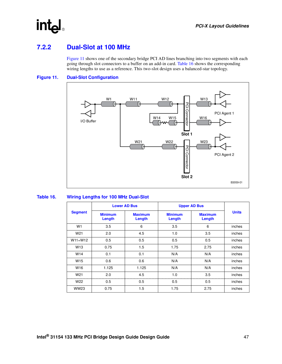
Figure 11 shows one of the secondary bridge PCI AD lines branching into two segments with each going through slot connectors to a buffer on an add-in card. Table 16 shows the corresponding wiring lengths to use as a reference. This two-slot design uses a balanced-star topology.
Figure 11. Dual-Slot Configuration
W1 | W11 | W12 |
| W13 |
|
|
| PCI |
|
|
|
| Connector | PCI Agent 1 |
I/O Buffer | W14 | W15 | W16 | |
|
|
| ||
|
|
|
| |
|
|
| Slot 1 |
|
| W21 | W22 |
| W23 |
|
|
| PCI |
|
|
|
| Connector | PCI Agent 2 |
|
|
|
| |
|
|
| Slot 2 |
|
|
|
|
|
Table 16. | Wiring Lengths for 100 MHz |
|
|
| ||
|
|
|
|
|
|
|
|
| Lower AD Bus | Upper AD Bus |
| ||
| Segment |
|
|
|
| Units |
| Minimum | Maximum | Minimum | Maximum | ||
|
|
| ||||
|
| Length | Length | Length | Length |
|
|
|
|
|
|
|
|
| W1 | 3.5 | 6 | 3.5 | 6 | inches |
|
|
|
|
|
|
|
| W21 | 2.0 | 4.5 | 1.0 | 3.5 | inches |
|
|
|
|
|
|
|
| W11+W12 | 0.5 | 0.5 | 0.5 | 0.5 | inches |
|
|
|
|
|
|
|
| W13 | 0.75 | 1.5 | 1.75 | 2.75 | inches |
|
|
|
|
|
|
|
| W14 | 0.1 | 0.1 | N/A | N/A | inches |
|
|
|
|
|
|
|
| W15 | 0.6 | 0.6 | N/A | N/A | inches |
|
|
|
|
|
|
|
| W16 | 1.125 | 1.125 | N/A | N/A | inches |
|
|
|
|
|
|
|
| W21 | 2.0 | 4.5 | 1.0 | 3.5 | inches |
|
|
|
|
|
|
|
| W22 | 0.5 | 0.5 | 0.5 | 0.5 | inches |
|
|
|
|
|
|
|
| WW23 | 0.75 | 1.5 | 1.75 | 2.75 | inches |
|
|
|
|
|
|
|
Intel® 31154 133 MHz PCI Bridge Design Guide Design Guide | 47 |