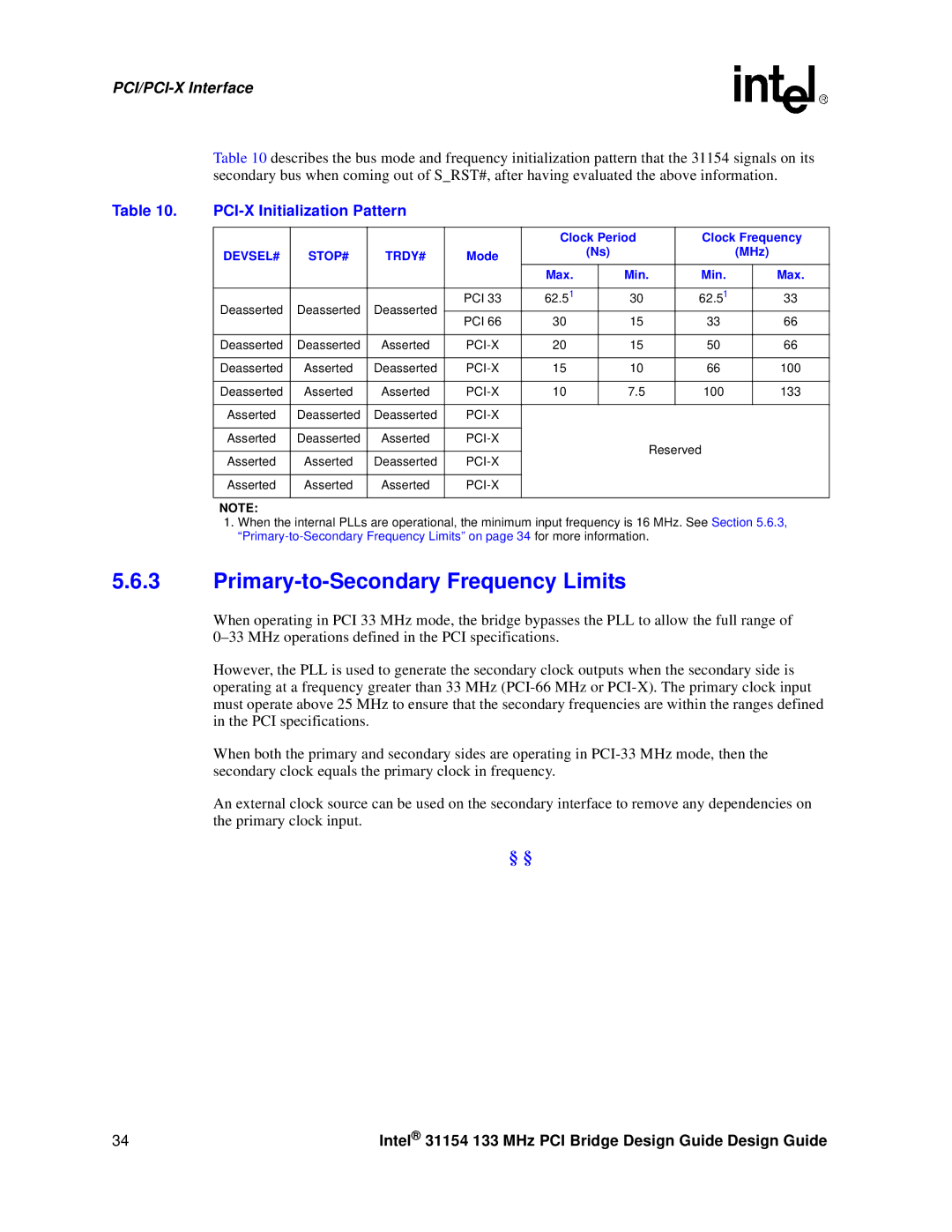
Table 10 describes the bus mode and frequency initialization pattern that the 31154 signals on its secondary bus when coming out of S_RST#, after having evaluated the above information.
Table 10. |
|
|
|
|
|
|
|
| ||
|
|
|
|
|
|
|
|
| ||
|
|
|
|
| Clock Period | Clock Frequency | ||||
| DEVSEL# | STOP# | TRDY# | Mode |
| (Ns) |
| (MHz) | ||
|
|
|
|
|
|
| ||||
|
|
|
|
| Max. |
| Min. | Min. |
| Max. |
|
|
|
|
|
|
|
|
|
|
|
| Deasserted | Deasserted | Deasserted | PCI 33 | 62.51 |
| 30 | 62.51 |
| 33 |
| PCI 66 | 30 |
| 15 | 33 |
| 66 | |||
|
|
|
|
|
| |||||
|
|
|
|
|
|
|
|
|
|
|
| Deasserted | Deasserted | Asserted |
| 20 |
| 15 | 50 |
| 66 |
|
|
|
|
|
|
|
|
|
|
|
| Deasserted | Asserted | Deasserted |
| 15 |
| 10 | 66 |
| 100 |
|
|
|
|
|
|
|
|
|
|
|
| Deasserted | Asserted | Asserted |
| 10 |
| 7.5 | 100 |
| 133 |
|
|
|
|
|
|
|
|
|
|
|
| Asserted | Deasserted | Deasserted |
|
|
|
|
|
|
|
|
|
|
|
|
|
|
|
|
|
|
| Asserted | Deasserted | Asserted |
|
|
| Reserved |
|
| |
|
|
|
|
|
|
|
|
| ||
| Asserted | Asserted | Deasserted |
|
|
|
|
| ||
|
|
|
|
|
|
| ||||
|
|
|
|
|
|
|
|
|
|
|
| Asserted | Asserted | Asserted |
|
|
|
|
|
|
|
|
|
|
|
|
|
|
|
|
|
|
| NOTE: |
|
|
|
|
|
|
|
|
|
1.When the internal PLLs are operational, the minimum input frequency is 16 MHz. See Section 5.6.3,
5.6.3Primary-to-Secondary Frequency Limits
When operating in PCI 33 MHz mode, the bridge bypasses the PLL to allow the full range of
However, the PLL is used to generate the secondary clock outputs when the secondary side is operating at a frequency greater than 33 MHz
When both the primary and secondary sides are operating in
An external clock source can be used on the secondary interface to remove any dependencies on the primary clock input.
§ §
34 | Intel® 31154 133 MHz PCI Bridge Design Guide Design Guide |
