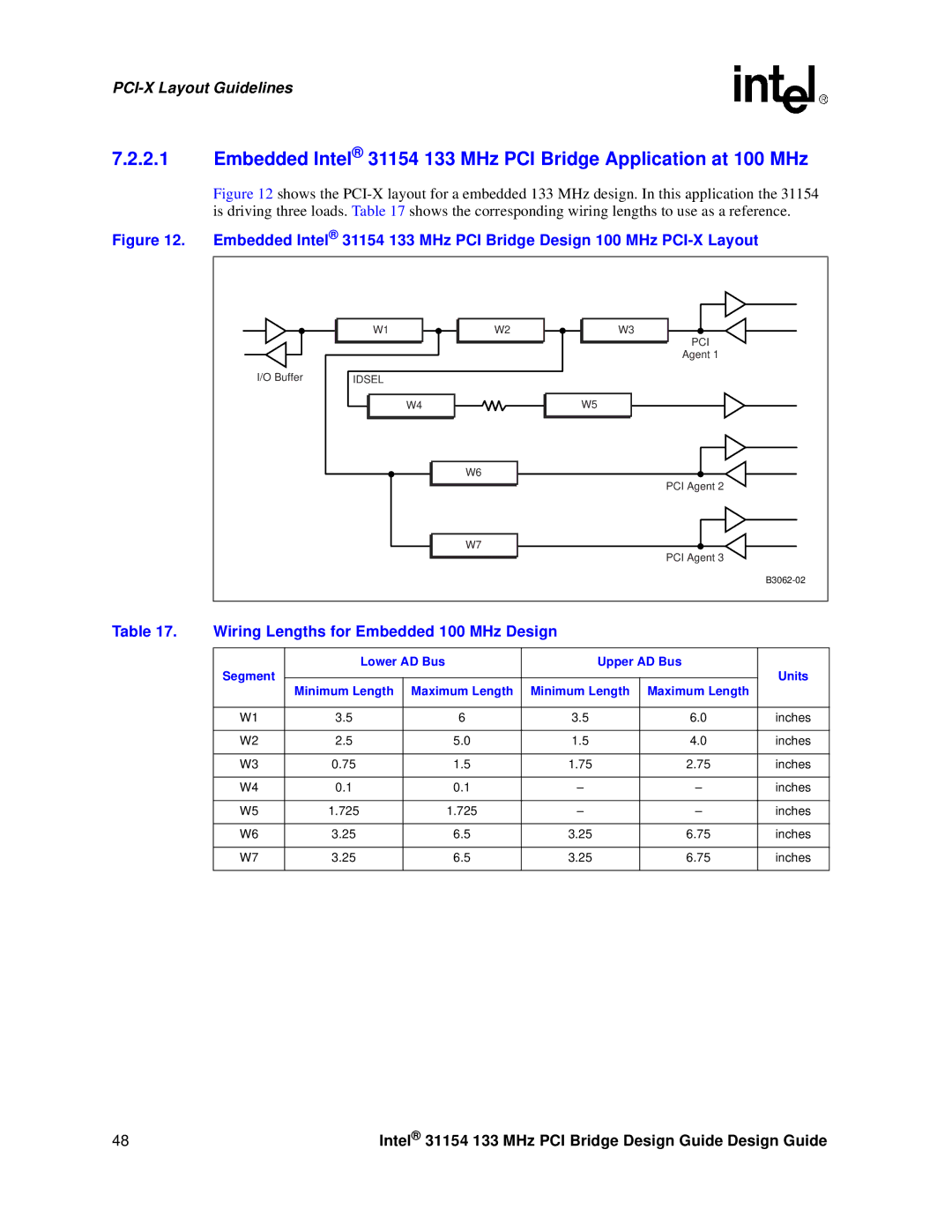
7.2.2.1Embedded Intel® 31154 133 MHz PCI Bridge Application at 100 MHz
Figure 12 shows the PCI-X layout for a embedded 133 MHz design. In this application the 31154 is driving three loads. Table 17 shows the corresponding wiring lengths to use as a reference.
Figure 12. Embedded Intel® 31154 133 MHz PCI Bridge Design 100 MHz PCI-X Layout
| W1 | W2 | W3 |
|
|
| PCI |
|
|
| Agent 1 |
I/O Buffer | IDSEL |
|
|
| W4 |
| W5 |
|
| W6 |
|
|
|
| PCI Agent 2 |
|
| W7 |
|
|
|
| PCI Agent 3 |
|
|
|
Table 17. | Wiring Lengths for Embedded 100 MHz Design |
|
| |||
|
|
|
|
|
|
|
| Segment | Lower AD Bus | Upper AD Bus | Units | ||
|
|
|
|
| ||
|
| Minimum Length | Maximum Length | Minimum Length | Maximum Length |
|
|
|
|
|
|
|
|
| W1 | 3.5 | 6 | 3.5 | 6.0 | inches |
|
|
|
|
|
|
|
| W2 | 2.5 | 5.0 | 1.5 | 4.0 | inches |
|
|
|
|
|
|
|
| W3 | 0.75 | 1.5 | 1.75 | 2.75 | inches |
|
|
|
|
|
|
|
| W4 | 0.1 | 0.1 | – | – | inches |
|
|
|
|
|
|
|
| W5 | 1.725 | 1.725 | – | – | inches |
|
|
|
|
|
|
|
| W6 | 3.25 | 6.5 | 3.25 | 6.75 | inches |
|
|
|
|
|
|
|
| W7 | 3.25 | 6.5 | 3.25 | 6.75 | inches |
|
|
|
|
|
|
|
48 | Intel® 31154 133 MHz PCI Bridge Design Guide Design Guide |