Terminations |
|
|
|
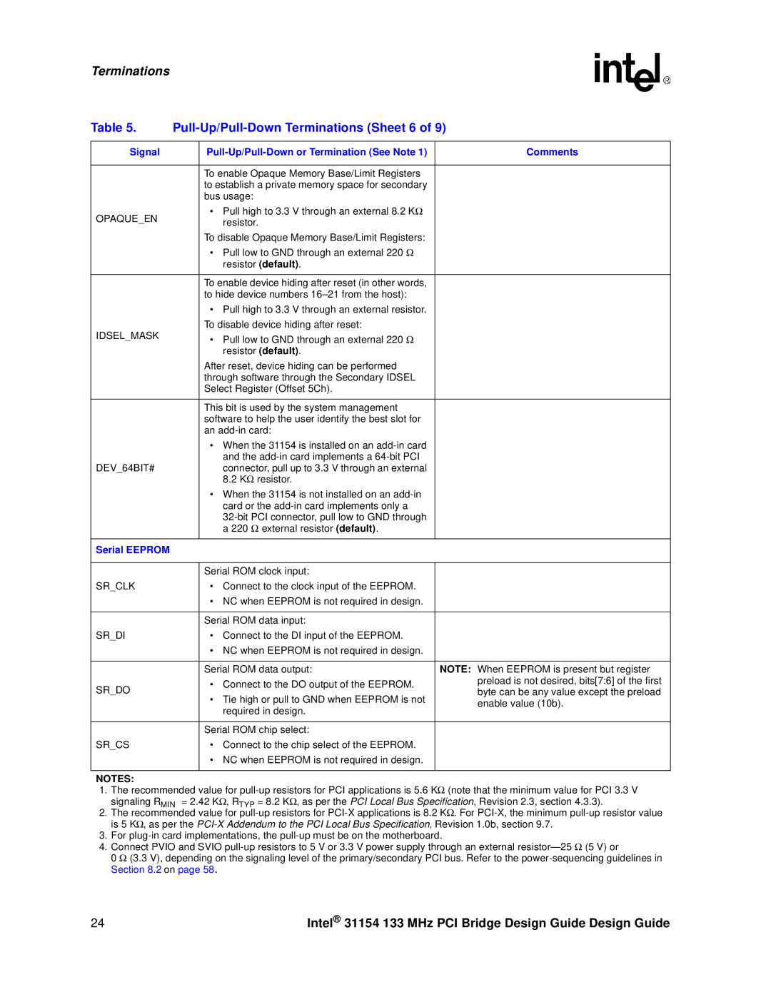
Table 5. |
| ||
|
|
|
|
Signal |
| Comments | |
|
|
|
|
|
| To enable Opaque Memory Base/Limit Registers |
|
|
| to establish a private memory space for secondary |
|
|
| bus usage: |
|
OPAQUE_EN |
| • Pull high to 3.3 V through an external 8.2 KΩ |
|
| resistor. |
| |
|
|
| |
|
| To disable Opaque Memory Base/Limit Registers: |
|
|
| • Pull low to GND through an external 220 Ω |
|
|
| resistor (default). |
|
|
|
|
|
|
| To enable device hiding after reset (in other words, |
|
|
| to hide device numbers |
|
|
| • Pull high to 3.3 V through an external resistor. |
|
IDSEL_MASK |
| To disable device hiding after reset: |
|
| • Pull low to GND through an external 220 Ω |
| |
|
|
| |
|
| resistor (default). |
|
|
| After reset, device hiding can be performed |
|
|
| through software through the Secondary IDSEL |
|
|
| Select Register (Offset 5Ch). |
|
|
|
|
|
|
| This bit is used by the system management |
|
|
| software to help the user identify the best slot for |
|
|
| an |
|
|
| • When the 31154 is installed on an |
|
|
| and the |
|
DEV_64BIT# |
| connector, pull up to 3.3 V through an external |
|
|
| 8.2 KΩ resistor. |
|
|
| • When the 31154 is not installed on an |
|
|
| card or the |
|
|
|
| |
|
| a 220 Ω external resistor (default). |
|
|
|
|
|
Serial EEPROM |
|
|
|
|
|
|
|
|
| Serial ROM clock input: |
|
SR_CLK |
| • Connect to the clock input of the EEPROM. |
|
|
| • NC when EEPROM is not required in design. |
|
|
|
|
|
|
| Serial ROM data input: |
|
SR_DI |
| • Connect to the DI input of the EEPROM. |
|
|
| • NC when EEPROM is not required in design. |
|
|
|
|
|
|
| Serial ROM data output: | NOTE: When EEPROM is present but register |
SR_DO |
| • Connect to the DO output of the EEPROM. | preload is not desired, bits[7:6] of the first |
| byte can be any value except the preload | ||
| • Tie high or pull to GND when EEPROM is not | ||
|
| enable value (10b). | |
|
| required in design. | |
|
|
| |
|
|
|
|
|
| Serial ROM chip select: |
|
SR_CS |
| • Connect to the chip select of the EEPROM. |
|
|
| • NC when EEPROM is not required in design. |
|
|
|
|
|
NOTES:
1.The recommended value for
2.The recommended value for
3.For
4.Connect PVIO and SVIO
0 Ω (3.3 V), depending on the signaling level of the primary/secondary PCI bus. Refer to the
24 | Intel® 31154 133 MHz PCI Bridge Design Guide Design Guide |