7.2.3Quad-Slots at 66 MHz
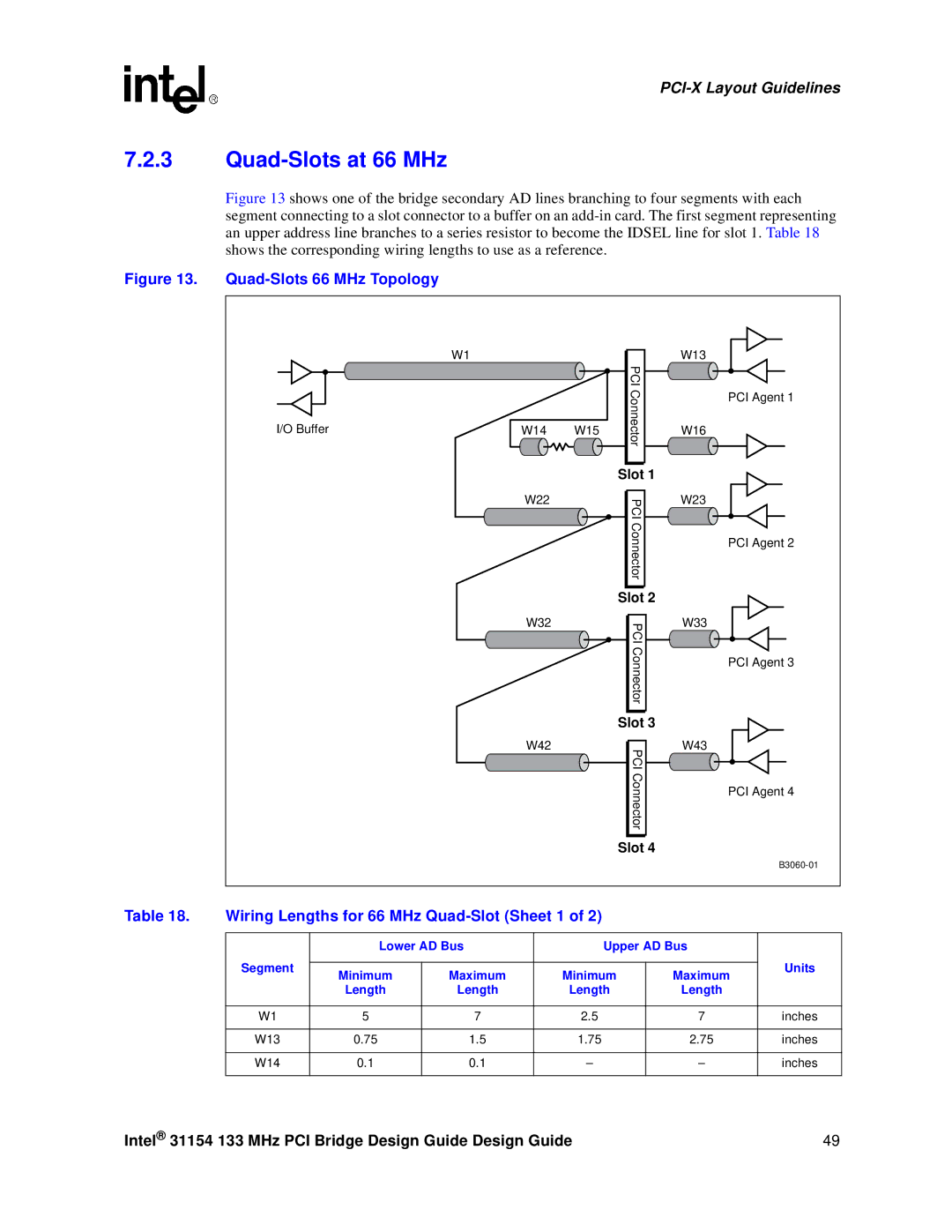
Figure 13 shows one of the bridge secondary AD lines branching to four segments with each segment connecting to a slot connector to a buffer on an add-in card. The first segment representing an upper address line branches to a series resistor to become the IDSEL line for slot 1. Table 18 shows the corresponding wiring lengths to use as a reference.
Figure 13. Quad-Slots 66 MHz Topology
| W1 |
|
| W13 |
|
|
| PCI |
|
|
|
| Connector | PCI Agent 1 |
I/O Buffer | W14 | W15 | W16 | |
|
|
|
| |
|
|
| Slot 1 |
|
| W22 |
| PCI | W23 |
|
|
|
| |
|
|
| Connector | PCI Agent 2 |
|
|
|
| |
|
|
| Slot 2 |
|
| W32 |
| PCI | W33 |
|
|
|
| |
|
|
| Connector | PCI Agent 3 |
|
|
|
| |
|
|
| Slot 3 |
|
| W42 |
| PCI | W43 |
|
|
|
| |
|
|
| Connector | PCI Agent 4 |
|
|
|
| |
|
|
| Slot 4 |
|
|
|
|
|
Table 18. Wiring Lengths for 66 MHz Quad-Slot (Sheet 1 of 2)
| Lower AD Bus | Upper AD Bus |
| |||
Segment |
|
|
|
| Units | |
Minimum | Maximum | Minimum | Maximum | |||
|
| |||||
| Length | Length | Length | Length |
| |
|
|
|
|
|
| |
W1 | 5 | 7 | 2.5 | 7 | inches | |
|
|
|
|
|
| |
W13 | 0.75 | 1.5 | 1.75 | 2.75 | inches | |
|
|
|
|
|
| |
W14 | 0.1 | 0.1 | – | – | inches | |
|
|
|
|
|
| |
Intel® 31154 133 MHz PCI Bridge Design Guide Design Guide | 49 |