IXP1200 Network Processor Family ATM OC-3/12/Ethernet IP Router Example Design
| Entry | Description |
| | |
| AAL | 5: ATM Adaptation Layer 5 |
| 0: VC is not open |
| |
| | |
| CRC | The CRC-32 syndrome associated with the PDU. It is saved in the VC table entry after a cell |
| is moved, and then retrieved and used when the next cell in the PDU is received. |
| |
| | |
| Cell Data11 | The last four bytes of the previous cell in this PDU. Used during re-assembly of PDUs to allow |
| 8-byte quadword burst writes to DRAM without using DRAM Read/Modify/Write instructions. |
| |
| | |
4.2Virtual Circuit Lookup Table Cache
4.2.1VC Cache Function
4.2.1.1OC-12 Configuration
The intent of the VC cache is not to reduce average latency but to account for back to back cells from the same VC. It is not possible to reduce average latency because the design has to account for worst case cache miss on every VC lookup anyway.
The OC-12 configuration caches the results of VC Table lookup operations in absolute registers. The intent of the VC cache is not to reduce average latency, but rather to account for back-to-back cells from the same VC. It is not possible to reduce average latency, because the design has to account for worst-case cache miss on every VC lookup. In this scenario, processing of the subsequent cell can only commence once processing of the previous cell has been completed and recorded in the VC Table Entry. In particular, the subsequent cell can access the VC Table Entry only after the previous cell has updated the buffer offset telling the cell where to go, and updated the CRC syndrome. The CRC syndrome is known only after the previous cell is done transferring from RFIFO to DRAM, and it must be known before the subsequent cell starts transferring from RFIFO to DRAM.
4.2.1.2OC-3 Configuration
The OC-3 configuration does not require, and thus does not enable, the VC Cache. In the OC-3 receiver, there is a single thread dedicated to each port. Therefore, by definition the cells coming in on each port are on different VCs and threads will thus never have to wait for access to the same VC Table Entry.
4.2.2VC Cache Structure
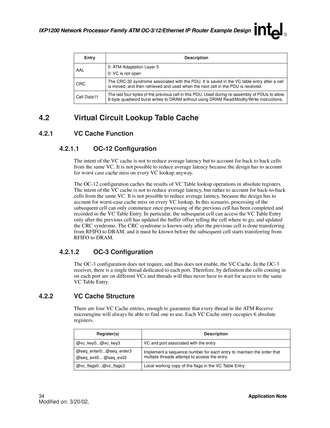
There are four VC Cache entries, enough to guarantee that every thread in the ATM Receive microengine will always be able to find one to use. Each VC Cache entry occupies 6 absolute registers.
Register(s) | Description |
| |
@vc_key0...@vc_key3 | VC and port associated with the entry |
| |
@seq_enter0...@seq_enter3 | Implement a sequence number for each entry to maintain the order that |
@seq_exit0... @seq_exit3 | multiple threads attempt to access the entry. |
| |
@vc_flags0...@vc_flags3 | Local working copy of the flags in the VC Table Entry. |
| |
