IXP1200 Network Processor Family ATM
2.3Software Partitioning
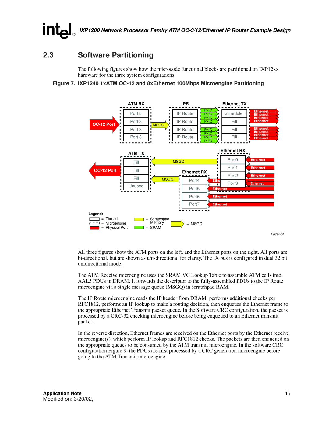
The following figures show how the microcode functional blocks are partitioned on IXP12xx hardware for the three system configurations.
Figure 7. IXP1240 1xATM OC-12 and 8xEthernet 100Mbps Microengine Partitioning
ATM RX
Port 8
Port 8
Port 8
Port 8
MSGQ
IPR
IP Route
IP Route
IP Route
IP Route
PktQ
PktQ
PktQ
PktQ
PktQ
PktQ
PktQ
PktQ
Ethernet TX
Scheduler
Fill
Fill
Fill
Ethernet
Ethernet
Ethernet
Ethernet
Ethernet
Ethernet
Ethernet
Ethernet
ATM TX
Fill
Fill
Fill
Unused
MSGQ
| Ethernet RX |
MSGQ |
|
Port4 | |
|
|
| Port5 |
|
|
| Port6 |
|
|
| Port7 |
|
|
Ethernet RX
Port0 | Ethernet |
Port1 | Ethernet |
Port2 | Ethernet |
Ethernet Port3 | Ethernet |
Ethernet |
|
Ethernet |
|
Ethernet |
|
Legend:
= Thread |
| = | Scratchpad |
|
= Microengine |
|
| Memory | = MSGQ |
= Physical Port |
| = | SRAM |
|
All three figures show the ATM ports on the left, and the Ethernet ports on the right. All ports are
The ATM Receive microengine uses the SRAM VC Lookup Table to assemble ATM cells into AAL5 PDUs in DRAM. It forwards the descriptor to the
The IP Route microengine reads the IP header from DRAM, performs additional checks per RFC1812, performs an IP lookup to make a routing decision, then enqueues the Ethernet frame to the appropriate Ethernet Transmit packet queue. In the Software CRC configuration, the packet is processed by a
In the reverse direction, Ethernet frames are received on the Ethernet ports by the Ethernet receive microengine(s), which perform IP lookup and RFC1812 checks. The packets are then enqueued on the appropriate queues to be consumed by the ATM transmit microengine. In the software CRC configuration Figure 9, the PDUs are first processed by a CRC generation microengine before going to the ATM Transmit microengine.
Application Note | 15 |
Modified on: 3/20/02,
