IXP1200 Network Processor Family ATM
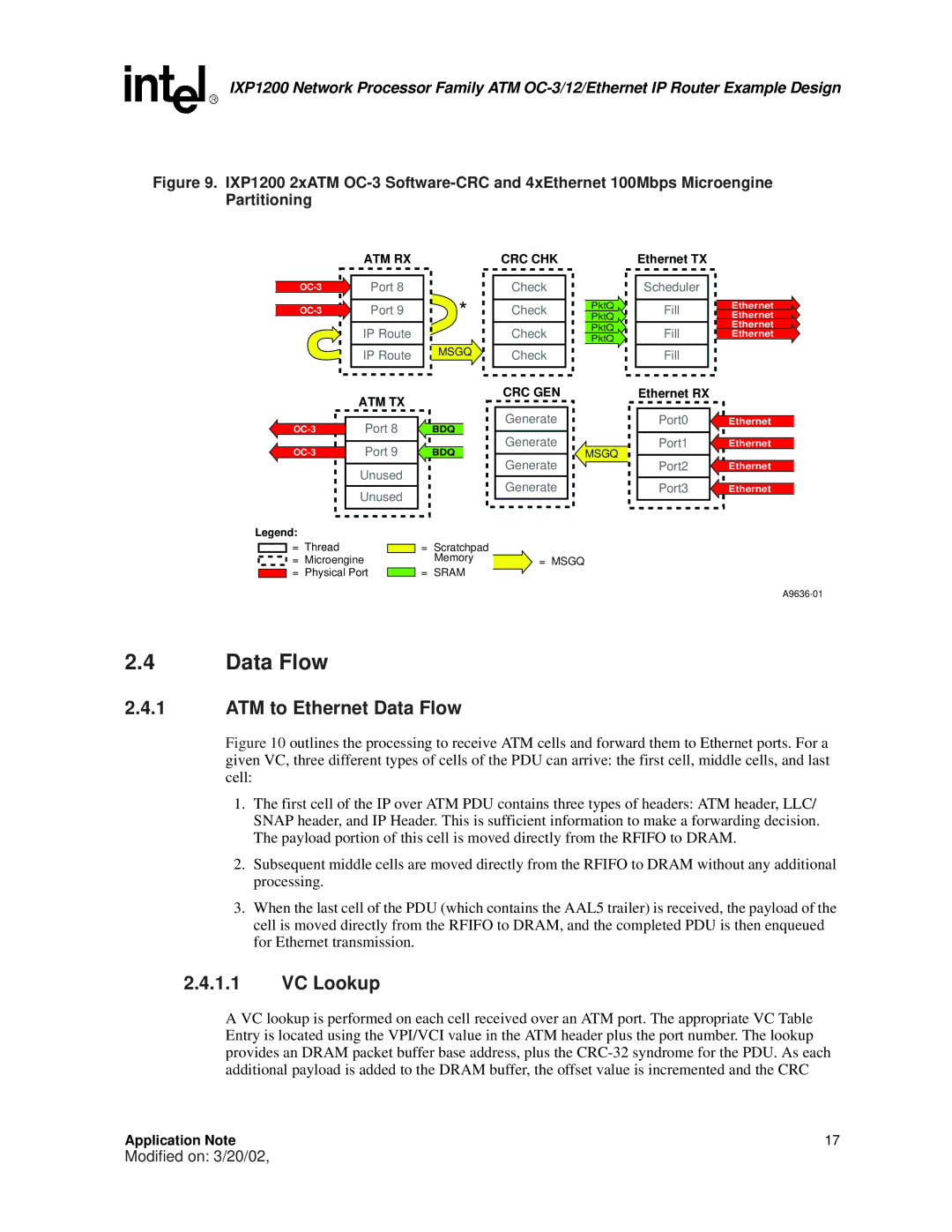
Figure 9. IXP1200 2xATM OC-3 Software-CRC and 4xEthernet 100Mbps Microengine Partitioning
ATM RX
Port 8 |
| |
Port 9 | * | |
| ||
| IP Route |
|
| IP Route | MSGQ |
CRC CHK
Check
Check
Check
Check
PktQ
PktQ
PktQ
PktQ
Ethernet TX
Scheduler
Fill
Fill
Fill
Ethernet
Ethernet
Ethernet
Ethernet
ATM TX
Port 8 | BDQ | |
Port 9 | BDQ | |
| Unused |
|
| Unused |
|
Legend: |
|
|
CRC GEN
Generate
Generate
Generate
Generate
MSGQ
Ethernet RX |
|
Port0 | Ethernet |
Port1 | Ethernet |
Port2 | Ethernet |
Port3 | Ethernet |
= Thread |
| = | Scratchpad |
|
= Microengine |
|
| Memory | = MSGQ |
= Physical Port |
| = | SRAM |
|
2.4Data Flow
2.4.1ATM to Ethernet Data Flow
Figure 10 outlines the processing to receive ATM cells and forward them to Ethernet ports. For a given VC, three different types of cells of the PDU can arrive: the first cell, middle cells, and last cell:
1.The first cell of the IP over ATM PDU contains three types of headers: ATM header, LLC/ SNAP header, and IP Header. This is sufficient information to make a forwarding decision. The payload portion of this cell is moved directly from the RFIFO to DRAM.
2.Subsequent middle cells are moved directly from the RFIFO to DRAM without any additional processing.
3.When the last cell of the PDU (which contains the AAL5 trailer) is received, the payload of the cell is moved directly from the RFIFO to DRAM, and the completed PDU is then enqueued for Ethernet transmission.
2.4.1.1VC Lookup
A VC lookup is performed on each cell received over an ATM port. The appropriate VC Table Entry is located using the VPI/VCI value in the ATM header plus the port number. The lookup provides an DRAM packet buffer base address, plus the
Application Note | 17 |
Modified on: 3/20/02,
