IXP1200 Network Processor Family ATM
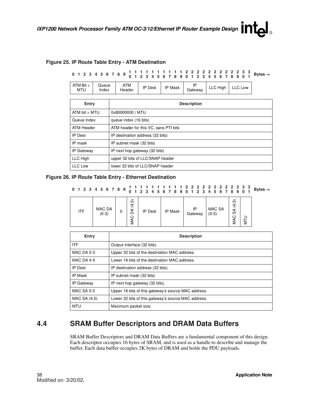
Figure 25. IP Route Table Entry - ATM Destination
0 1 2 3 4 5 6 7 8 9 | 1 | 1 | 1 | 1 | 1 | 1 | 1 | 1 | 1 | 1 | 2 | 2 | 2 | 2 | 2 | 2 | 2 | 2 | 2 | 2 | 3 | 3 | Bytes |
0 | 1 | 2 | 3 | 4 | 5 | 6 | 7 | 8 | 9 | 0 | 1 | 2 | 3 | 4 | 5 | 6 | 7 | 8 | 9 | 0 | 1 |
ATM Bit + | Queue |
MTU | Index |
|
|
ATM
Header
IP Dest
IP Mask
IP
Gateway
LLC High LLC Low
Entry | Description |
|
|
ATM bit + MTU | 0x80000000 MTU |
|
|
Queue Index | queue index (16 bits) |
|
|
ATM Header | ATM header for this VC, sans PTI bits |
|
|
IP Dest | IP destination address (32 bits) |
|
|
IP mask | IP subnet mask (32 bits) |
|
|
IP Gateway | IP next hop gateway (32 bits) |
|
|
LLC High | upper 32 bits of LLC/SNAP header |
|
|
LLC Low | lower 32 bits of LLC/SNAP header |
|
|
Figure 26. IP Route Table Entry - Ethernet Destination
0 1 2 3 4 5 6 7 8 9 | 1 | 1 | 1 | 1 | 1 | 1 | 1 | 1 | 1 | 1 | 2 | 2 | 2 | 2 | 2 | 2 | 2 | 2 | 2 | 2 | 3 | 3 | Bytes |
0 | 1 | 2 | 3 | 4 | 5 | 6 | 7 | 8 | 9 | 0 | 1 | 2 | 3 | 4 | 5 | 6 | 7 | 8 | 9 | 0 | 1 |
ITF
MAC DA
0
MAC DA (4,5)
IP Dest
IP Mask
IP
Gateway
MAC SA
MAC SA (4,5)
MTU
Entry | Description |
|
|
ITF | Output interface (32 bits). |
|
|
MAC DA | Upper 32 bits of the destination MAC address. |
|
|
MAC DA | Lower 16 bits of the destination MAC address. |
|
|
IP Dest | IP destination address (32 bits). |
|
|
IP Mask | IP subnet mask (32 bits) |
|
|
IP Gateway | IP next hop gateway (32 bits). |
|
|
MAC SA | Upper 16 bits of this gateway’s source MAC address. |
|
|
MAC SA (4,5) | Lower 32 bits of this gateway’s source MAC address. |
|
|
MTU | Maximum packet size. |
|
|
4.4SRAM Buffer Descriptors and DRAM Data Buffers
SRAM Buffer Descriptors and DRAM Data Buffers are a fundamental component of this design. Each descriptor occupies 16 bytes of SRAM, and is used as a handle to describe and manage the buffer. Each data buffer occupies 2K bytes of DRAM and holds the PDU payloads.
38 | Application Note |
Modified on: 3/20/02,