IXP1200 Network Processor Family ATM
In the
In the
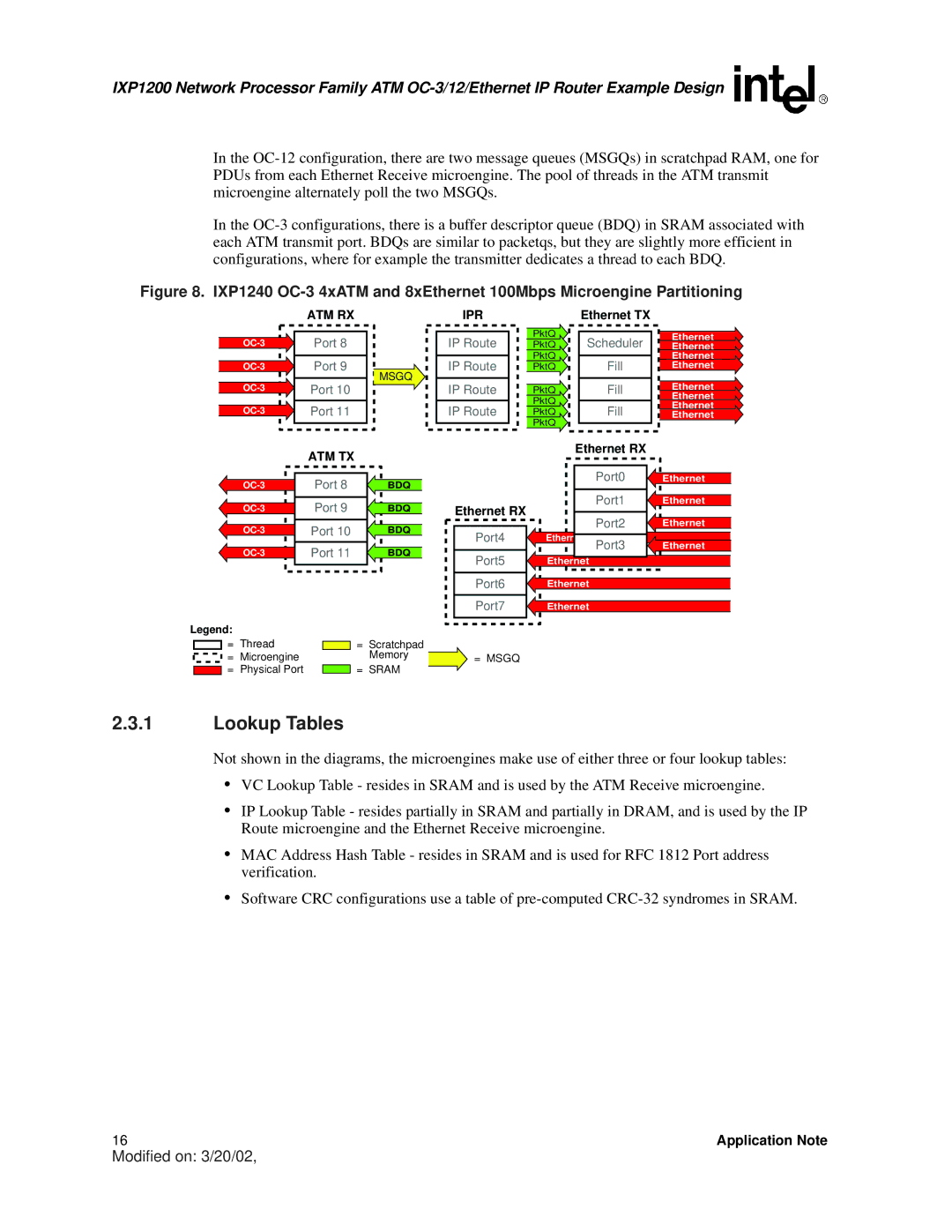
Figure 8. IXP1240 OC-3 4xATM and 8xEthernet 100Mbps Microengine Partitioning
| ATM RX |
Port 8 | |
Port 9 | |
MSGQ | |
Port 10 | |
Port 11 |
IPR
IP Route
IP Route
IP Route
IP Route
PktQ
PktQ
PktQ
PktQ
PktQ
PktQ
PktQ
PktQ
Ethernet TX
Scheduler
Fill
Fill
Fill
Ethernet
Ethernet
Ethernet
Ethernet
Ethernet
Ethernet
Ethernet
Ethernet
ATM TX
Port 8 | BDQ | |
Port 9 | BDQ | |
Port 10 | BDQ | |
Port 11 | BDQ |
Legend:
Ethernet RX
Port4 |
Port5 |
Port6 |
Port7 |
Ethernet RX |
| |
| Port0 | Ethernet |
| Port1 | Ethernet |
| Port2 | Ethernet |
Ethernet | Port3 | Ethernet |
Ethernet |
|
|
Ethernet |
|
|
Ethernet |
|
|
= Thread |
| = | Scratchpad |
|
= Microengine |
|
| Memory | = MSGQ |
= Physical Port |
| = | SRAM |
|
2.3.1Lookup Tables
Not shown in the diagrams, the microengines make use of either three or four lookup tables:
•VC Lookup Table - resides in SRAM and is used by the ATM Receive microengine.
•IP Lookup Table - resides partially in SRAM and partially in DRAM, and is used by the IP Route microengine and the Ethernet Receive microengine.
•MAC Address Hash Table - resides in SRAM and is used for RFC 1812 Port address verification.
•Software CRC configurations use a table of
16 | Application Note |
Modified on: 3/20/02,