System Rear
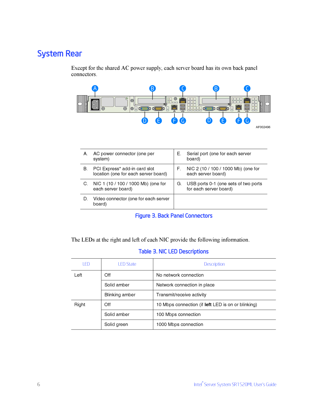
Except for the shared AC power supply, each server board has its own back panel connectors.
A | B | C | B | C |
D | E | F G | D | E | F G |
AF002496
A. AC power connector (one per | E. | Serial port (one for each server |
system) |
| board) |
|
|
|
B. PCI Express* | F. | NIC 2 (10 / 100 / 1000 Mb) (one for |
location (one for each server board) |
| each server board) |
|
|
|
C. NIC 1 (10 / 100 / 1000 Mb) (one for | G. | USB ports |
each server board) |
| for each server board) |
D.Video connector (one for each server board)
Figure 3. Back Panel Connectors
The LEDs at the right and left of each NIC provide the following information.
|
| Table 3. NIC LED Descriptions | |
|
|
|
|
LED | LED State |
| Description |
|
|
|
|
Left | Off |
| No network connection |
|
|
|
|
| Solid amber |
| Network connection in place |
|
|
|
|
| Blinking amber |
| Transmit/receive activity |
|
|
|
|
Right | Off |
| 10 Mbps connection (if left LED is on or blinking) |
|
|
|
|
| Solid amber |
| 100 Mbps connection |
|
|
|
|
| Solid green |
| 1000 Mbps connection |
|
|
|
|
6 | Intel® Server System SR1520ML User’s Guide |