Notes:
•Use caution when connecting cables to make sure you do not pinch any cables.
•For data cable routing information, see “Cable Routing” on page 67.
•For power cable routing information, see “Cable Routing” on page 67.
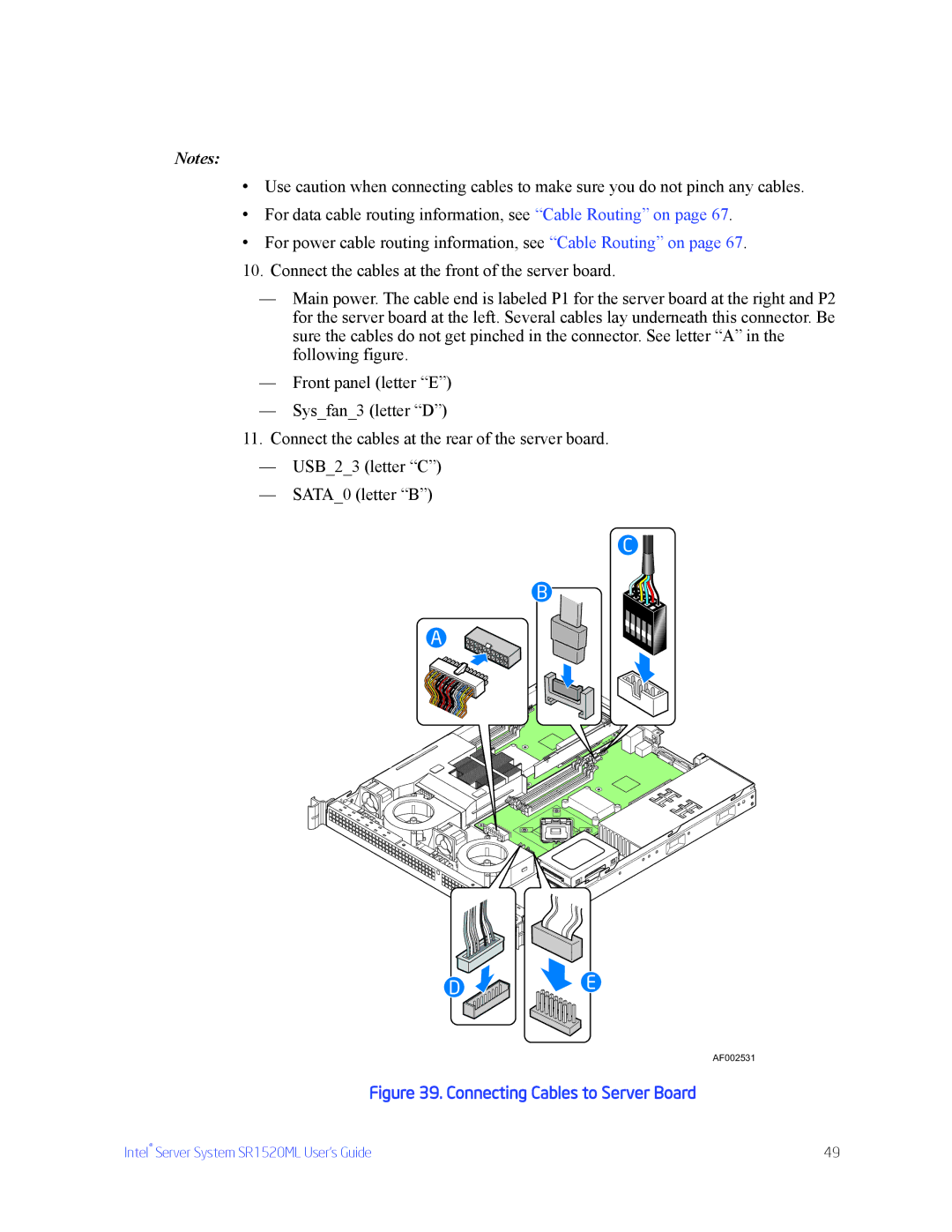
10.Connect the cables at the front of the server board.
—Main power. The cable end is labeled P1 for the server board at the right and P2 for the server board at the left. Several cables lay underneath this connector. Be sure the cables do not get pinched in the connector. See letter “A” in the following figure.
—Front panel (letter “E”)
—Sys_fan_3 (letter “D”)
11.Connect the cables at the rear of the server board.
—USB_2_3 (letter “C”)
—SATA_0 (letter “B”)
C ![]()
B
A
D![]()
![]()
![]() E
E
AF002531
Figure 39. Connecting Cables to Server Board
Intel® Server System SR1520ML User’s Guide | 49 |