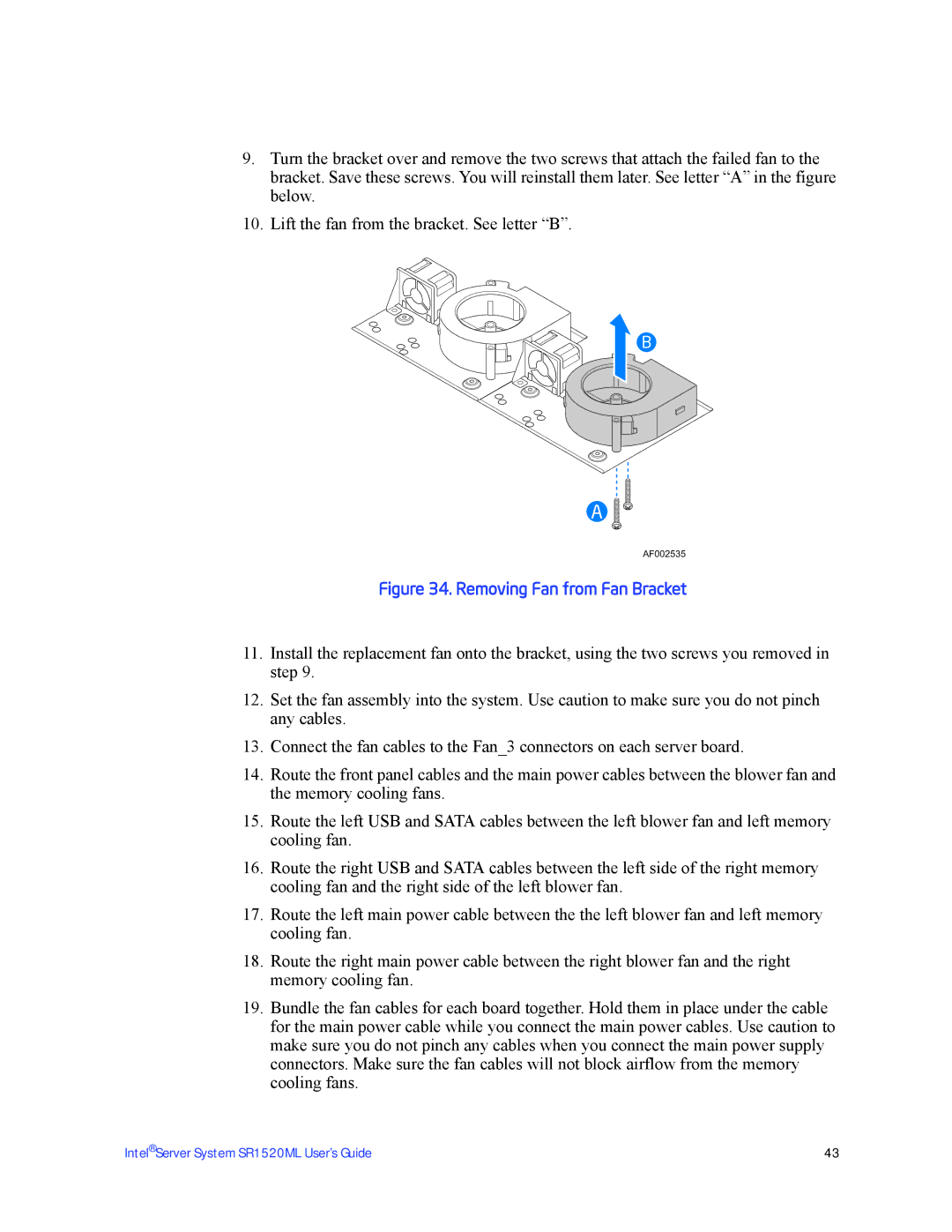
9.Turn the bracket over and remove the two screws that attach the failed fan to the bracket. Save these screws. You will reinstall them later. See letter “A” in the figure below.
10.Lift the fan from the bracket. See letter “B”.
B
A
AF002535
Figure 34. Removing Fan from Fan Bracket
11.Install the replacement fan onto the bracket, using the two screws you removed in step 9.
12.Set the fan assembly into the system. Use caution to make sure you do not pinch any cables.
13.Connect the fan cables to the Fan_3 connectors on each server board.
14.Route the front panel cables and the main power cables between the blower fan and the memory cooling fans.
15.Route the left USB and SATA cables between the left blower fan and left memory cooling fan.
16.Route the right USB and SATA cables between the left side of the right memory cooling fan and the right side of the left blower fan.
17.Route the left main power cable between the the left blower fan and left memory cooling fan.
18.Route the right main power cable between the right blower fan and the right memory cooling fan.
19.Bundle the fan cables for each board together. Hold them in place under the cable for the main power cable while you connect the main power cables. Use caution to make sure you do not pinch any cables when you connect the main power supply connectors. Make sure the fan cables will not block airflow from the memory cooling fans.
Intel® Server System SR1520ML User’s Guide | 43 |