|
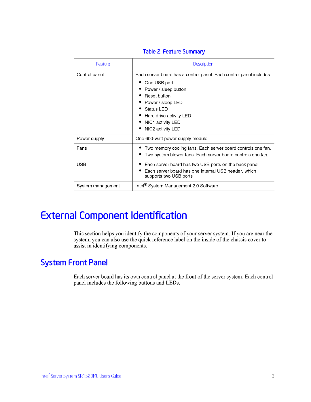
| Table 2. Feature Summary |
|
|
|
Feature |
| Description |
|
| |
Control panel | Each server board has a control panel. Each control panel includes: | |
| • | One USB port |
| • Power / sleep button | |
| • | Reset button |
| • Power / sleep LED | |
| • | Status LED |
| • Hard drive activity LED | |
| • | NIC1 activity LED |
| • | NIC2 activity LED |
|
| |
Power supply | One | |
|
|
|
Fans | • | Two memory cooling fans. Each server board controls one fan. |
| • Two system blower fans. Each server board controls one fan. | |
|
|
|
USB | • | Each server board has two USB ports on the back panel |
| • Each server board has one internal USB header, which | |
|
| supports two USB ports |
|
| |
System management | Intel® System Management 2.0 Software | |
External Component Identification
This section helps you identify the components of your server system. If you are near the system, you can also use the quick reference label on the inside of the chassis cover to assist in identifying components.
System Front Panel
Each server board has its own control panel at the front of the server system. Each control panel includes the following buttons and LEDs.
Intel® Server System SR1520ML User’s Guide | 3 |
