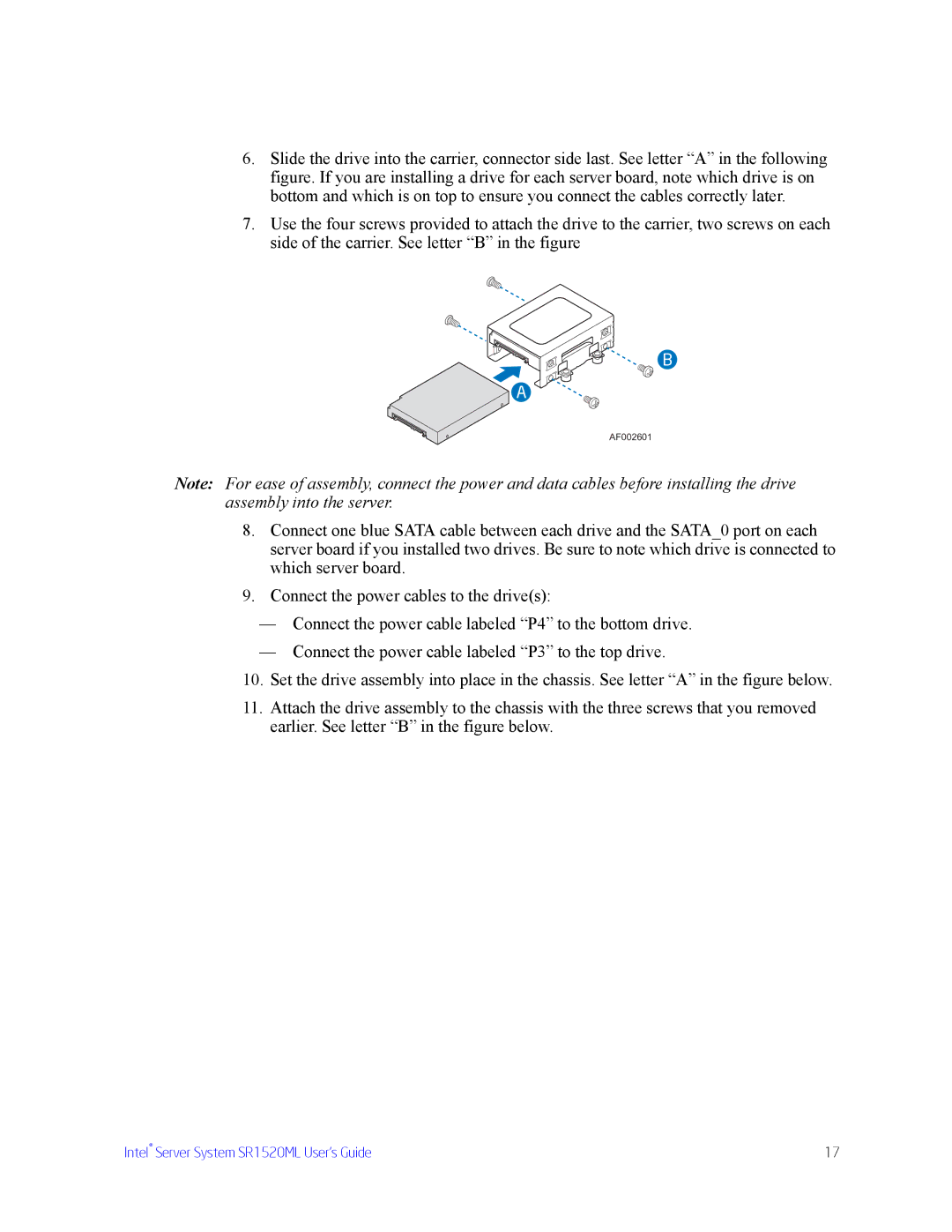
6.Slide the drive into the carrier, connector side last. See letter “A” in the following figure. If you are installing a drive for each server board, note which drive is on bottom and which is on top to ensure you connect the cables correctly later.
7.Use the four screws provided to attach the drive to the carrier, two screws on each side of the carrier. See letter “B” in the figure
B
A
AF002601
Note: For ease of assembly, connect the power and data cables before installing the drive assembly into the server.
8.Connect one blue SATA cable between each drive and the SATA_0 port on each server board if you installed two drives. Be sure to note which drive is connected to which server board.
9.Connect the power cables to the drive(s):
—Connect the power cable labeled “P4” to the bottom drive.
—Connect the power cable labeled “P3” to the top drive.
10.Set the drive assembly into place in the chassis. See letter “A” in the figure below.
11.Attach the drive assembly to the chassis with the three screws that you removed earlier. See letter “B” in the figure below.
Intel® Server System SR1520ML User’s Guide | 17 |