DN9340E/DN9344E
Digital Equaliser
Operator Manual
Klark Teknik Klark Teknik Building
Page
IMPORTANT SAFETY INSTRUCTIONS
Page
DECLARATION OF CONFORMITY
We, Telex Communications UK Limited
Directives
Test Standards
Page
CONTENTS
Thank You For Using This Klark Teknik Product
8. STORING AND RECALLING SETTINGS DN9340E
SETUP MENU DN9340E
DN9340E AND DN9344E MASTER/SLAVE REMOTE CONTROL
DN9340E AND DN9344E REMOTE CONTROL SETUP
SIGNAL FLOW DN9344E
SET UP MENU DN9344E
TECHNICAL SPECIFICATION
Page
Safety Warning
Installation Considerations
After Unpacking
Please ensure that you read and follow the
Page
Quick Reference
1.1. DN9340E Front Panel
11HOME SETUP button
BYPASS button
7SETUP button
1.2. DN9344E Front Panel
Quick Reference
DN9340E & DN9344E Key Features
2.2. Key Features
2. INTRODUCING THE DN9340E/DN9344E
2.1. Host Software Versions
DN9340E & DN9344E Key Features
Remote control operation
Space efficiency
Interface to Midas consoles
3.1. EQ Access and Displays
Controls, Connectors, Indicators DN9340E
3. FRONT PANEL DN9340E
Controls, Connectors, Indicators DN9340E
selected channel both channels if linked. When a
BYPASS button
Soft keys
Controls, Connectors, Indicators DN9340E
HOME SETUP button
STORE and RECALL
buttons
3.4. PC Port, Metering and Power
Controls, Connectors, Indicators DN9340E
4. REAR PANEL DN9340E
Controls, Connectors, Indicators DN9340E
Signal Flow DN9340E
5. SIGNAL FLOW DN9340E
6. OPERATION DN9340E
Operation DN9340E
6.1. Home Page
6.1.3Touchstrip Operation on the Home Page
Operation DN9340E
In the home page, the touchstrip is inoperative
Operation DN9340E
6.2. Graphic Equalisation
6.2.1Soft Key Functions
Operation DN9340E
Automatic features page
EQ - Flat page
Operation DN9340E
6.2.3Grouping
Operation DN9340E
6.3. Parametric Equalisation
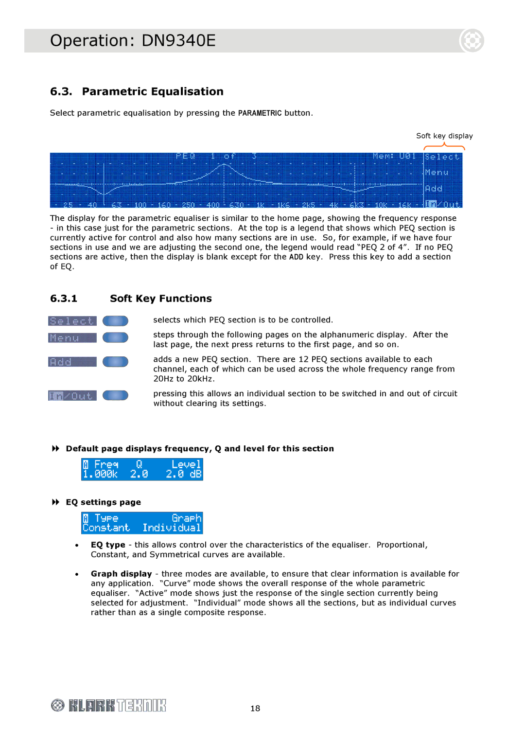
6.3.1Soft Key Functions
Operation DN9340E
EQ remove page
Operation DN9340E
6.4. Dynamic Equalisation
6.4.1Soft Key Functions
Operation DN9340E
EQ settings page
Time constants page
6.5. Filters
Operation DN9340E
6.5.1“Create Filter” function
6.5.2Soft Key Functions
Filter settings page
Operation DN9340E
6.5.3Touchstrip operation with Filters
Filter remove page
6.6. Metering
Operation DN9340E
6.7. Clear Down Sequence
Operation DN9340E
7. SETUP MENU DN9340E
Setup Menu DN9340E
7.1. General
Setup Menu DN9340E
7.2. Comms channel Page
7.2.1Remote control via a PC
Setup Menu DN9340E
7.2.2Using a DN9340E for master control
To select a master remote communications channel
To select a slave communications channel
7.3. Front Panel lock Page
Setup Menu DN9340E
To set a Panel Lock
To remove the Panel Lock
Setup Menu DN9340E
7.4. Analogue/Digital Input Select Page
To change the input source
7.6. Presets lock Page
7.5. Digital Output Clock Select Page
Setup Menu DN9340E
To set a Presets lock
7.7. LCD contrast adjustment Page
7.9. Delay options Page
7.8. Naming Pages 7 and
Setup Menu DN9340E
7.10. Power-upLogo Page
7.11. Ethernet Settings Pages 11 and
Setup Menu DN9340E
7.11.1Ethernet IP Address Page
7.11.2Ethernet Subnet Mask Setup Page
Setup Menu DN9340E
To check and edit the Subnet Mask
8.STORING AND RECALLING SETTINGS DN9340E
Using the DN9340E Memories
1 Press RECALL
Remote Control
9.1. Connections
9.2. Addresses
9.3. Data model
9.4. Getting started
Remote Control
Setting the master unit on-line
On a DN9340E
9.5. Operation
9.6. System naming
Remote Control
To set up the names
9.7. Copy channel function
9.8. Solo Tracking operation
Remote Control
To set up the assignment
10.1. Overview
10.2. HELIX DN9340E/DN9344E unit interconnections
Remote Control
10.DN9340E AND DN9344E REMOTE CONTROL SETUP
Remote Control
The diagram below shows a typical example of the HELIX DN9340/DN9344E units connected in a daisy chain configuration
10.3. Ethernet Connection
Remote Control
10.3.2Ethernet connection - wireless option
10.3.1Ethernet connection - standard
Remote Control
Before you can control the DN9340E from your remote software, there are number of configuration settings to check on the DN9340E units
10.4. Serial Connection Option
Remote Control
10.4.2Connection and Configuration Procedure
10.4.1Serial connection details
11. FRONT PANEL DN9344E
Controls, Connectors, Indicators DN9344E
SETUP button
Controls, Connectors, Indicators DN9344E
2Display mode indicators blue for sections 1 and
12.REAR PANEL DN9344E
Controls, Connectors, Indicators DN9344E
Signal Flow DN9344E
13. SIGNAL FLOW DN9344E
15.SET UP MENU DN9344E
Operation DN9344E
14. OPERATION DN9344E
15.1. General
Operation DN9344E
To select a remote communications channel
To enable the Contact Closure RELAY mode
Operation DN9344E
15.3. Password Page Page
15.4. Analogue/Digital Input Select Pages 3 and
To set a password
To change the settings for Inputs 1A and 1B
To change the settings for Output
15.5. Digital Output Clock Select Pages 5 and
Operation DN9344E
Operation DN9344E
15.6. Ethernet Settings Page
15.6.2Subnet Mask Page
Application Notes
16.1. Dynamic EQ
As an example, consider Figure 2, which shows the Helix applying a boost at low signal levels which is automatically ‘wound out’ at high level
Application Notes
Application Notes
Without changing modes or making any other selections, we can make the unit operate ‘the other way up’ just by selecting suitable values for the two thresholds and levels see Figure
16.2. What do we mean by all these Q types?
Application Notes
Proportional Q
Application Notes
Constant Q
Application Notes
Symmetrical Q
16.3. What is AES/EBU?
Application Notes
Technical Specification DN9340E
17.1. DN9340E
Technical Specification DN9340E
Delay
Input Gain
Filters
Technical Specification DN9344E
17.2. DN9344E
Technical Specification DN9344E
Voltage
Service Information
18.1. Battery